


Using the LCD
Learn how to use Sparki's LCD to display information.
Lessons You Should Know

Introduction
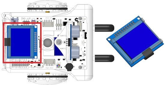
Sparki features a small LCD display that will let us make drawings, write text, and show the status of other components of the robot, such as the readings from its sensors.
In this lesson you will learn the basics of how to use the LCD display. This will become a useful element once we start to work with sensors in the upcoming lessons.
Pixels
Every display out there is composed by pixels. Pixels are the smallest points that we can control in a display, be it a cellphone screen, a computer monitor, a TV, or Sparki’s LCD. In our tiny LCD, pixels can be in one of two states: ON or OFF. By turning different pixels ON and OFF, we can draw something, or write text into the display.
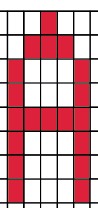
For example, the following image shows capital “A” letter made of square pixels, like the ones in Sparki’s LCD:
How can we set a pixel ON and OFF? There are several commands that we can use in our programs to control the pixels, and we will learn more about them soon later in this lesson. But first, we need to understand how each pixel is identified in order to control it.
Pixels Coordinates
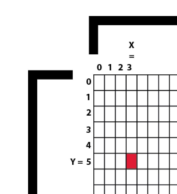
How can you tell Sparki which pixel to change? Using a system called coordinates, in this case X (horizontal, or left to right position) and Y coordinates (vertical, or top to bottom coordinates). We type coordinates as these two numbers, X and Y, typed as (X,Y). In the image below, we have a starting (or zero) point. This point is (0,0), or an X value of 0, followed by a Y number of 0. The pixel below has an X value of 3, and a Y value of 5, so we talk about it as the (3,5) pixel:
Here you can see the complete Sparki display. It is 128 pixels wide and 64 pixels tall:
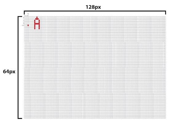
Here are some examples of pixels with their corresponding coordinates:
- The pixel in the upper-left corner is (0, 0).
- The pixel in the first left-right row and in the last top-bottom column is (127, 0).
- The pixel in the last left-right row and in the first top-bottom column is (0, 63).
- The pixel in the last left-right row and in the last top-bottom column is (127, 63).
Try entering different coordinates for a bunch of pixels. You may want to get used to the coordinate system to the point where you can identify if a pixel will appear on the upper half or the lower half of the screen as well as knowing if it will be on the right or left hand side just by taking a look at the pixel coordinates.
Left or Right? It might be easiest to take a look at the width of the LCD screen. The middle of the screen (in regards to left and right) is at pixel number 64. So if the first pixel coordinate is higher than the number 64 then the number will appear on the right hand side of the screen, if it is lower than the number 64 it will appear on the left hand side of the screen.
Upper or Lower? Now let’s look at the height of the pixel screen. The middle of the screen (in regards to up and down) is at pixel 32. This means that if the second pixel coordinate is higher than 32 it will appear on the bottom of the LCD screen. If the second pixel coordinate is lower than 32 it will appear on the top of the LCD screen.
Actually Making a Pixel- Use the command drawPixel( ); to draw a single pixel. For example, the command drawPixel(3,5); will draw a pixel at the coordinates we talked about in the beginning of this section- an X value of 3 and a Y value of 5.
High Level Commands
Pixels are a small part of the screen. If you were to write a letter, or draw a circle, or almost anything else by turning on and off each pixel it needed, that would be a LOT of work! That’s why even though we could still write (and read) individual pixels, we will not be doing that most of the time. Instead, we will be using simpler Sparki commands to draw things, without having to turn on and off each pixel one by one. Imagine the number of lines of code you would need to write in order to create a square that is 20 pixels by 20 pixels? It would take 400 lines of code just to make a simple square!
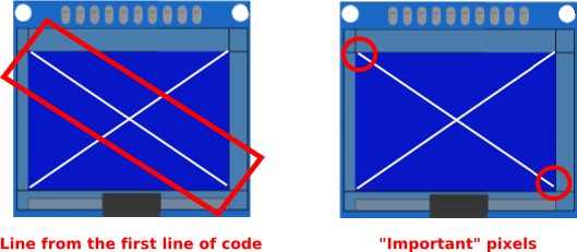
Let’s start with a small example: drawing some lines to make a large X on the display, corner to corner:
#include; // include the sparki library void setup() { } void loop() { sparki.clearLCD(); // wipe the LCD clear sparki.drawLine(0,0, 127,63); sparki.drawLine(0,63, 127,0); sparki.updateLCD(); // put the drawings on the screen delay(1000); }

So, how does this work? Let’s take a general look at the code:
- First, everything is written in the loop. Why? Because the display needs to be updated from time to time. As you can see, there is a delay(1000) instruction at the end of the program. This means that the command that updates the display (the sparki.updateLCD command) doesn’t need to be executed very often. It just needs to be there when you want the display to be drawn again. Without the sparki.updateLCD command the new information would never make its way onto the LCD screen. We will see better examples of this later on in the lesson.
- Second, before we can effectively draw the lines, we have to wipe the LCD clear using the sparki.clearLCD instruction. If you don’t do this then Sparki will leave the previous drawing on the LCD and just draw the new lines over it. That isn’t a big deal for our two lines, but if we wanted to change the position of the lines then without the sparki.clearLCD instruction we could draw a new line but the old line would stay on the screen. (We’ll take a look at sparki.clearLCD a little more in the animation section of this lesson.)
- Finally, in the middle of this program are the line drawing instructions themselves. As you can see, the sparki.drawLine command receives 4 (integer) numbers as parameters. What are these numbers? They are the coordinates belonging to the “important” pixels of our lines. By important pixels we mean the pixels at the beginning and at the beginning and end of each line. Let’s take a look at the first line of code- sparki.drawline(0,0, 127, 63); The first two numbers (0, 0) are located at the upper left corner of the LCD screen and the second set of numbers (127, 63) are located at the lower right corner of the LCD screen. Sparki fills in the pixels that connect these two dots in a straight line.
So what about circles, rectangles, or even filled zones? Let’s try the following code, and then you can experiment a bit with the coordinates and dimensions of the different elements drawn there:
#include; // include the sparki library void setup() { } void loop() { sparki.clearLCD(); sparki.drawRect(5,5, 30,10); sparki.drawRectFilled(15,17, 30,10); sparki.drawCircle(55,30, 5); sparki.drawCircle(20,45, 12); sparki.drawCircleFilled(90,40, 20); sparki.updateLCD(); delay(1000); }
Of course, you can always go to the File->Examples->LCD menu in the SparkiDuino software, and play with the examples there.
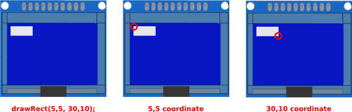
Rectangles- Let’s take a look at how these lines of code which draw rectangles work. There are four coordinates inside the parenthesis. The first two numbers are the coordinates of one of the corners of the rectangle. The second two numbers are the coordinates of the corner that is the diagonal opposite of the first. Really, the second set of numbers could be the upper left corner and the first set of numbers could be the lower left corner of the rectangle and you could draw the same rectangle using- sparki.drawRect(30,10, 5,5);
as you can with the command-
sparki.drawRect(30,10, 5,5);
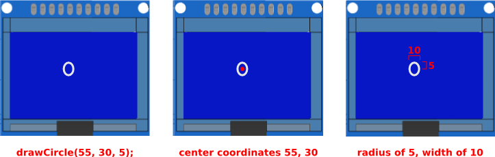
Circles- Now let’s take a look at the code that draws circles. We’ll focus on the command sparki.drawCircle(55, 30, 5); The first two numbers are the X and Y coordinates of the center of the circle Sparki is going to draw. This is exactly the same as the code for drawing a pixel. The main difference is that Sparki will draw a circle around this point. The radius of the circle is the third number, 5. So this code will draw a circle that is 10 pixels tall and 10 pixels wide with a center at 55, 30.
Writing Text and Numbers
Another important thing that we can do with the LCD display is writing text and numbers. This is very useful, especially once we start to work with Sparki’s sensors since we can easily use the LCD to display the values of the sensors Sparki is reading. This way, if something is not working as we expect in a program using one or more sensors, we can see the exact readings on the display. You can also use the LCD to print out where Sparki is in the code you have written.
There are two ways of writing text: The first would be to write each individual letter. The easier way is just printing the text, and the Sparki LCD will automatically position each printed line after the other in the LCD. Please note that in the example below, the sparki.println() function can both print text strings and numbers (integers and floats):
#include; // include the sparki library void setup() { } void loop() { sparki.clearLCD(); // wipe the LCD clear sparki.print("abc"); sparki.println("def"); sparki.println(123); sparki.println(456.5); sparki.updateLCD(); // put the drawings on the screen delay(1000); }
The other way of writing a text in the LCD is a bit more tricky, but it will enable us to position a character or a text string anywhere on the display:
#include; // include the sparki library void setup() { } void loop() { sparki.clearLCD(); // wipe the LCD clear sparki.drawChar(10, 1, 'a'); sparki.drawChar(20, 2, 'b'); sparki.drawChar(30, 3, 'c'); sparki.drawString(40, 4, "123"); sparki.updateLCD(); // put the drawings on the screen delay(1000); }
With this second way of displaying letters or Strings you can make the words, letters or numbers appear anywhere, which is useful if you are animating something with text or making a diagram of something (maybe a diagram of Sparki) and you want to label parts of the diagram. With the first method you have no control of where the text will show up, but it’s great if you just need to display information and don’t care what it looks like or where it is on the screen. When using the second method the first two numbers are X and Y coordinates, while the third value inside the parenthesis is the text you wish to display.
Please take into account that if we want to print numbers using this last method, we need to convert them as shown in the following example, using the string class from the standard Arduino API:
#include; // include the sparki library void setup() { } void loop() { sparki.clearLCD(); // wipe the LCD clear sparki.drawChar(10, 1, 'a'); sparki.drawChar(20, 2, 'b'); sparki.drawChar(30, 3, 'c'); char text[20]; String number = String(123); number.toCharArray(text, sizeof(text)); sparki.drawString(40, 4, text); sparki.updateLCD(); // put the drawings on the screen delay(1000); }
(NOTE: if you don’t yet understand the conversions used here, don’t worry! We are just showing a little more advanced way of visualizing numbers, but we will primarily rely on the simpler print() function in our future lessons)
Simple Animations
The last thing that we will learn here is how to do some small and (very) simple animations with our display. Let’s start with a simple circle that will move across the screen:
Here is the code:
#include; // include the sparki library int x = 0; void setup() { } void loop() { sparki.clearLCD(); // wipe the LCD clear if (x < 127) x++; else x = 0; sparki.drawCircleFilled(x,32, 10); // small filled circle vertically centered sparki.updateLCD(); // put the drawings on the screen delay(100); // delay for the animation }
See the trick? We have used a variable which changes instead of a fixed value for the X coordinate. We increment that variable (called "x') each time through the loop cycle. Once the variable reaches its maximum value (which we have set as 127 here), we reset 'x' to zero. This way, the circle crosses the small screen over and over again.
You can experiment modifying both the delay time and the x variable increment. Regarding the delay time, please note that if you do it too fast, you will not give enough time to the microprocessor to render the images on the LCD display, but push it a bit so you can learn about its graphical processing capabilities!
How could you change the code that effects x so that the ball moves faster? How about slower? Don't just think about it, try out different code on Sparki and see how it works!
What about making the ball bounce back and forth instead of starting at one side of the screen and traveling to the other side? Here's some code to get you started on that project, it makes the ball start on one side of the screen and bounce when it hits the right hand side. Making it bounce when it hits the left hand side is up to you.
#include; // include the sparki library int x = 0; boolean hitRight; void setup() { } void loop() { sparki.clearLCD(); // wipe the LCD clear if (x < 127 && hitRight == false) //changed this x++; else x--; //changed this if(x > 126) //added this hitRight = true; //added this sparki.drawCircleFilled(x,32, 10); // small filled circle vertically centered sparki.updateLCD(); // put the drawings on the screen delay(100); // delay for the animation }
Another interesting thing that we can animate besides the position of an object is its size. Let's try the following program to animate the height of a vertical bar (made with a rectangle):
#include; // include the sparki library int y = 10; void setup() { } void loop() { sparki.clearLCD(); // wipe the LCD clear if (y < 60) y += 10; else y = 0; sparki.drawRectFilled(10,0, 15, y); sparki.updateLCD(); // put the drawings on the screen delay(150); // delay for the animation }
Instructions Summary
Finally, here are all the instructions provided with the Sparki software to work with the LCD display:
sparki.clearLCD();
sparki.updateLCD();

sparki.drawPixel(xPixel, yPixel);
sparki.readPixel(xPixel, yPixe);
sparki.drawChar(xPixel, yLine, char);
sparki.drawString(xPixel, yLine, *char);
sparki.drawLine(xStart, yStart, xEnd, yEnd);
sparki.drawRect(xCenter, yCenter, width, heigh);
sparki.drawRectFilled(xCenter, yCenter, width, height);
sparki.drawCircle(xCenter, yCenter, radius);
sparki.drawCircleFilled(xCenter, yCenter, radius);
sparki.drawBitmap(xStart, yStart, *bitmap, width, height);
Having Fun with Animation
Drawing Eyes- Now let's do a little bit of animation that gives Sparki some eyes and makes them look right or left depending on which way Sparki turns. The first things we need to draw are some plain old eyes. We can do that using the drawCircle( ) command. We'll draw to large unfilled circles for the eyes with two smaller filled circles inside for the pupils.
#include; // include the sparki library void setup() { } void loop() { sparki.clearLCD(); // wipe the LCD clear sparki.drawCircle(32, 25, 20); //eye 1 sparki.drawCircle(96, 25, 20); //eye 2 sparki.drawCircleFilled(32, 25, 5); //pupil 1 sparki.drawCircleFilled(96, 25, 5); //pupil 2 sparki.drawLine(15,15, 49,15);//eyelid 1 sparki.drawLine(79,15, 112,15);//eyelid 2 sparki.updateLCD(); // put the drawings on the screen delay(100); // delay for the animation }
Making the Eyes Blink- Now, for fun, we'll make the eyes blink. That means we have to move the code around a little and make a counter so that Sparki only blinks every once in a while.
#include; // include the sparki library int blinkCounter; void setup() { } void loop() { sparki.clearLCD(); // wipe the LCD clear if(blinkCounter > 195) blinkEyes(); else drawEyes(); sparki.updateLCD(); // put the drawings on the screen delay(100); // delay for the animation blinkCounter ++; //make counter count up if(blinkCounter == 200){ blinkCounter = 0; //reset counter } } void drawEyes() { sparki.drawCircle(32, 25, 20); //eye 1 sparki.drawCircle(96, 25, 20); //eye 2 sparki.drawCircleFilled(32, 25, 5); //pupil 1 sparki.drawCircleFilled(96, 25, 5); //pupil 2 sparki.drawLine(15,15, 49,15);//eyelid 1 sparki.drawLine(79,15, 112,15);//eyelid 2 } void blinkEyes() { sparki.drawCircle(32, 25, 20); //eye 1 sparki.drawCircle(96, 25, 20); //eye 2 sparki.drawLine(12,24, 52,24);//eyelid 1 sparki.drawLine(76,24, 115,24);//eyelid 2 sparki.drawLine(12,25, 52,25);//eyelid 3 sparki.drawLine(76,25, 115,25);//eyelid 4 }
See how useful counters are? If you're really looking for a challenge try adding eyelashes to your animation. Don't forget that the eyelashes will need to move when Sparki blinks!
Making the Eyes Look Right and Left- Ok, now we're going to combine what we learned in the moving ball section and our current code. We'll write some code that makes Sparki's pupil's look right and left while Sparki turns left and right. Here's the code that deals with right hand turns, I'll leave the left hand turns up to you.
#include; // include the sparki library int blinkCounter; int x = 0; //integer to keep track of how much Sparki's eyes have moved boolean lookRight; //flag to trigger looking right boolean lookLeft; //flag to trigger looking left boolean lookCenterFromRight; //flag to tell Sparki to look back at the middle after looking right boolean lookCenterFromLeft; //flag to tell Sparki to look back at the middle after looking left void setup() { } void loop() { sparki.clearLCD(); // wipe the LCD clear //start drawing eyes code if(blinkCounter > 195) blinkEyes(); else if(lookRight || lookCenterFromRight) lookEyes(); else drawEyes(); //end drawing eyes code sparki.updateLCD(); // put the drawings on the screen delay(100); // delay for the animation blinkCounter ++; //make counter count up if(blinkCounter == 200){ blinkCounter = 0; //reset counter } if(blinkCounter == 100) { lookRight = true; } } void drawEyes() { sparki.drawCircle(32, 25, 20); //eye 1 sparki.drawCircle(96, 25, 20); //eye 2 sparki.drawCircleFilled(32, 25, 5); //pupil 1 sparki.drawCircleFilled(96, 25, 5); //pupil 2 sparki.drawLine(15,15, 49,15);//eyelid 1 sparki.drawLine(79,15, 112,15);//eyelid 2 } void blinkEyes() { sparki.drawCircle(32, 25, 20); //eye 1 sparki.drawCircle(96, 25, 20); //eye 2 sparki.drawLine(12,24, 52,24);//eyelid 1 sparki.drawLine(76,24, 115,24);//eyelid 2 sparki.drawLine(12,25, 52,25);//eyelid 3 sparki.drawLine(76,25, 115,25);//eyelid 4 } void lookEyes() { sparki.drawCircle(32, 25, 20); //eye 1 sparki.drawCircle(96, 25, 20); //eye 2 sparki.drawCircleFilled(32 + x, 25, 5); //pupil 1 (add X to change position sparki.drawCircleFilled(96 + x, 25, 5); //pupil 2 (add X to change position sparki.drawLine(15,15, 49,15);//eyelid 1 sparki.drawLine(79,15, 112,15);//eyelid 2 if(lookRight) { sparki.moveRight(3); //actually move Sparki x++; //move pupils the to the right if(x >= 15)//keep the pupils inside the eyes { lookRight = false; //done looking right lookCenterFromRight = true; //now look back to the center } } if(lookCenterFromRight) { x--; //move the pupils to the left if(x == 0) //if Sparki is looking back at the center lookCenterFromRight = false; //turn off looking to center } }
The lookEyes( ) function moves the pupils to the right and turns Sparki to the right when lookRight is true. Once Sparki has looked to the right as far as it can lookRight becomes false and lookCenterFromRight becomes true. If lookCenterFromRight is true Sparki's pupils will move back to the center and then turn lookCenterFromRight false.
There are a bunch of different ways you can write this code to achieve the same effect. (In fact, you don't really need to write the commands that draw the larger unfilled circles that are Sparki's eyes more than once.) Here's another challenge- how can you write this code so that Sparki's pupils pause while it is looking as far to the right as possible?
(Hint, remember that Sparki doesn't actually draw the pupils until the sparki.updateLCD( ) command so you can manipulate the position of the pupils all you like and any changes you make won't show up on the LCD until the sparki.updateLCD( ) command occurs.
Additional Challenges
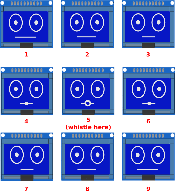
After you've made Sparki look to the left, how about giving your Sparki face a nose and a mouth? Looking for an animation challenge? Try giving Sparki a straight line for a mouth and every once in a while making the line get shorter until it is only seven or eight pixels wide and then making a circle that gets larger until Sparki looks like it is whistling. (Hint, you may need to draw two lines and a circle between then to do this.) During this portion of the animation you can even make Sparki's piezo buzzer whistle a little tune to match the animation! Here's a picture to help you figure out what each frame in your animation should look like-
Final Code for Eyes and Movement
Extra Activities
- Figure out how to draw a small Earth and Moon system where the Moon rotates around the Earth.
- Make some random animations with lines and squares. Tip: You can use the random function from the Arduino API.
- Take some of the programs to move Sparki (from the Moving the Robot lesson) and try to print the speeds of the motors every 100 milliseconds in the LCD.