
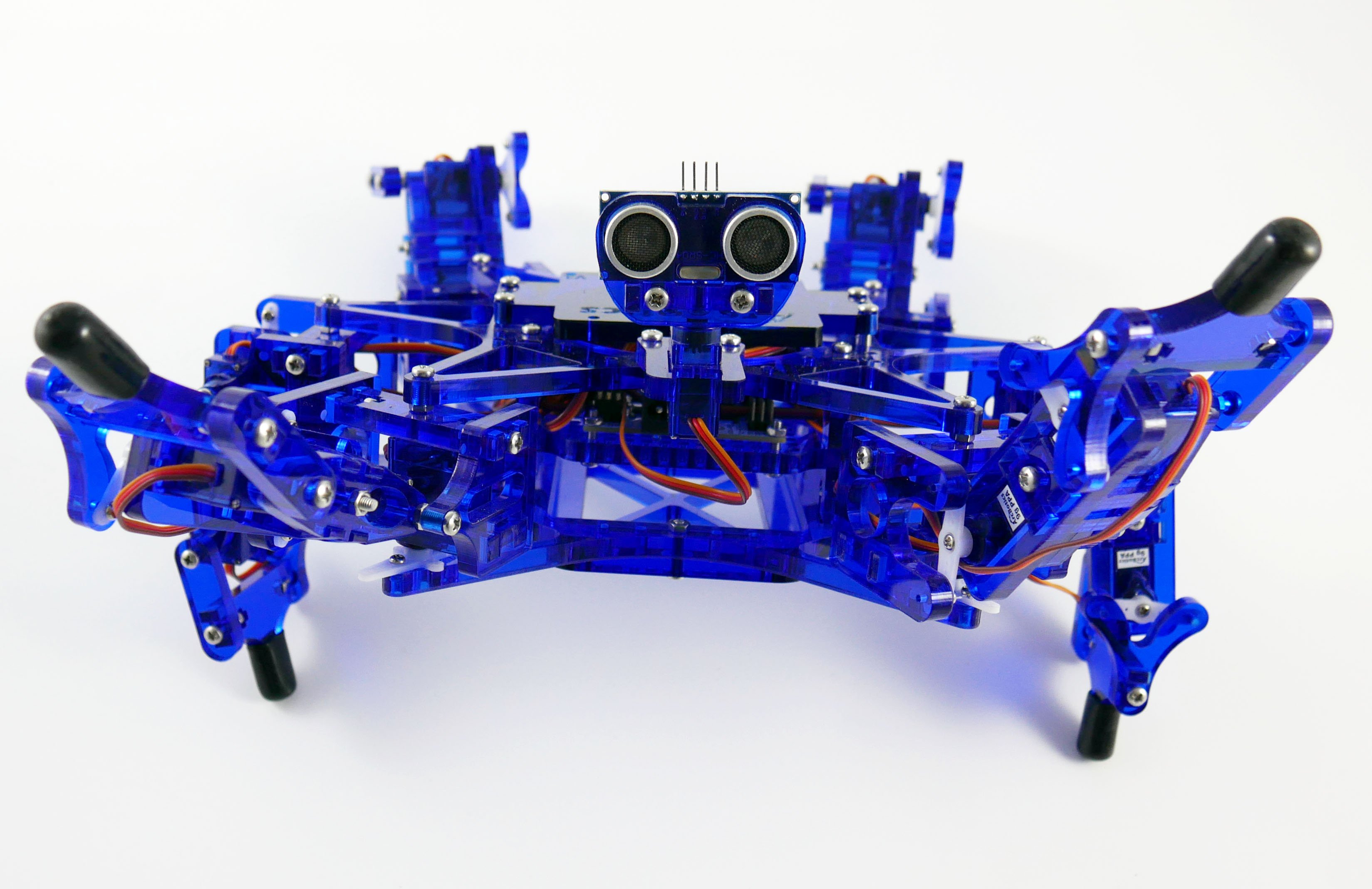
Building Your Hexy the Hexapod
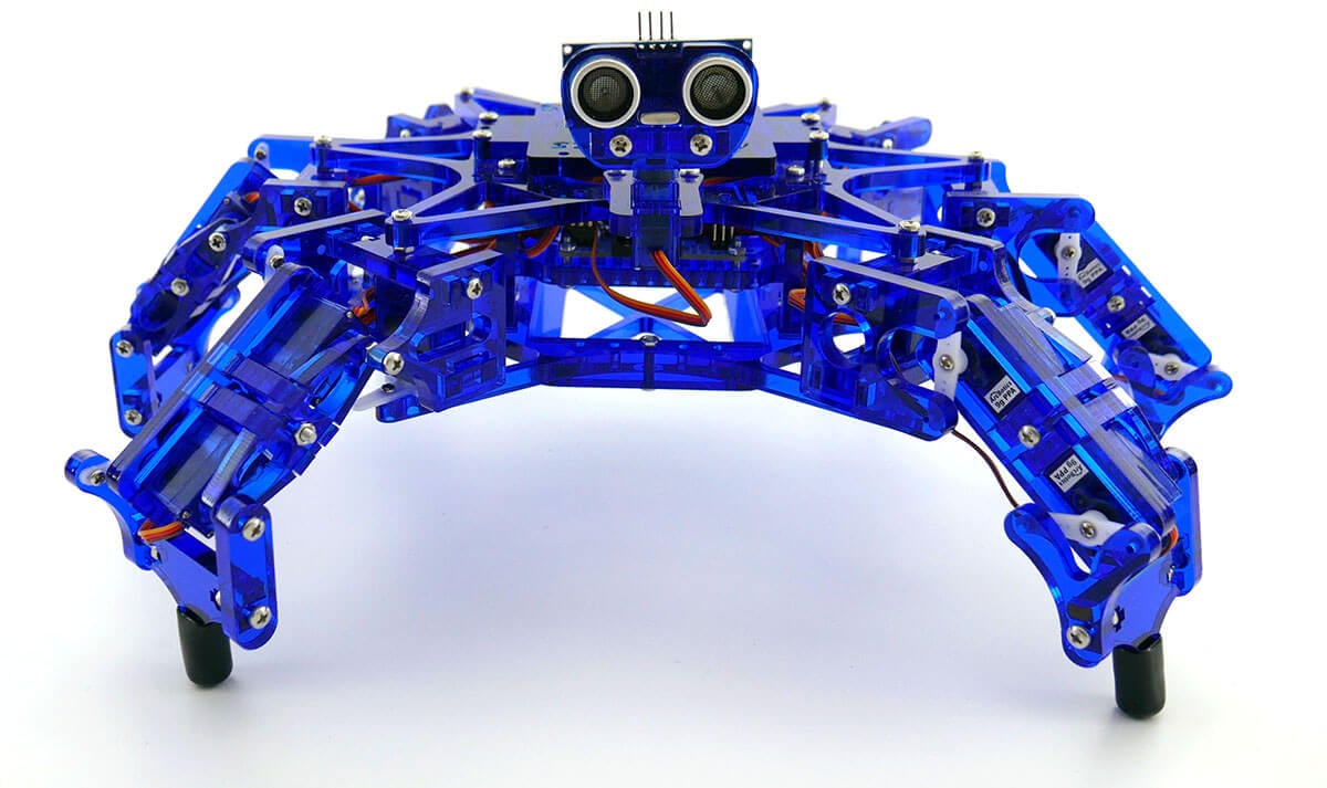
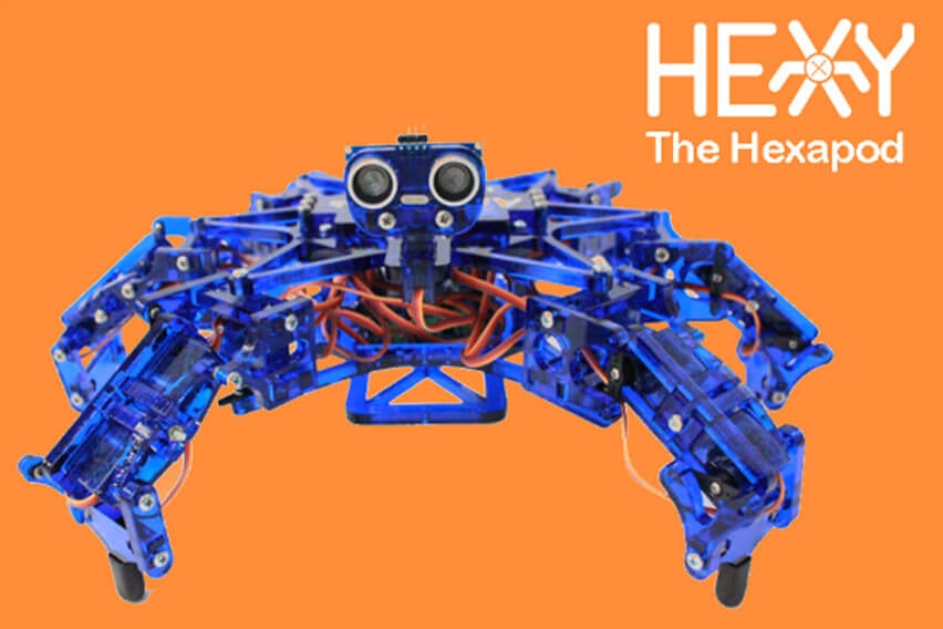
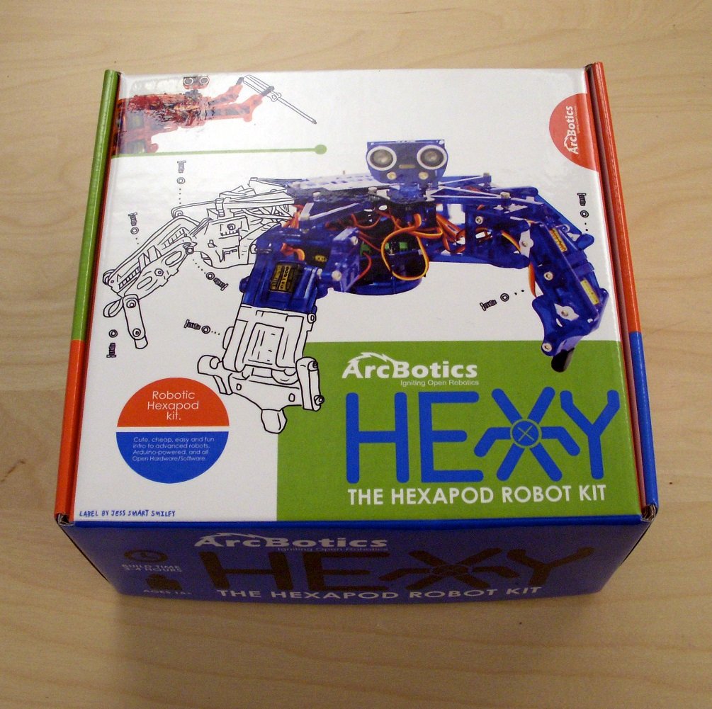
Hello! You’ve gotten your hands on Hexy the Hexapod, a great way to learn how robots without wheels work. First you’ve got to put it together, so clear some space on your lab bench (or kitchen table) and get ready to build!
Here are the different instructions for building Hexy that we’ll be following:
- Hexy’s Parts
- Hexy’s Legs
- Hexy’s Feet
- Hexy’s Hips
- Hexy’s Body
- Hexy’s Controller
- Attaching Hexy’s Legs
- Hexy’s Batteries
- Hexy’s Head
- Plugging in Hexy’s Servos
- Hexy’s Accessories (Ultrasonic sensor and Bluetooth module)
If you pause and want to come back to building Hexy you can use the links above to easily find your place again.
Step 1 – Check your Kit
Unpack your kit and make sure everything is there.
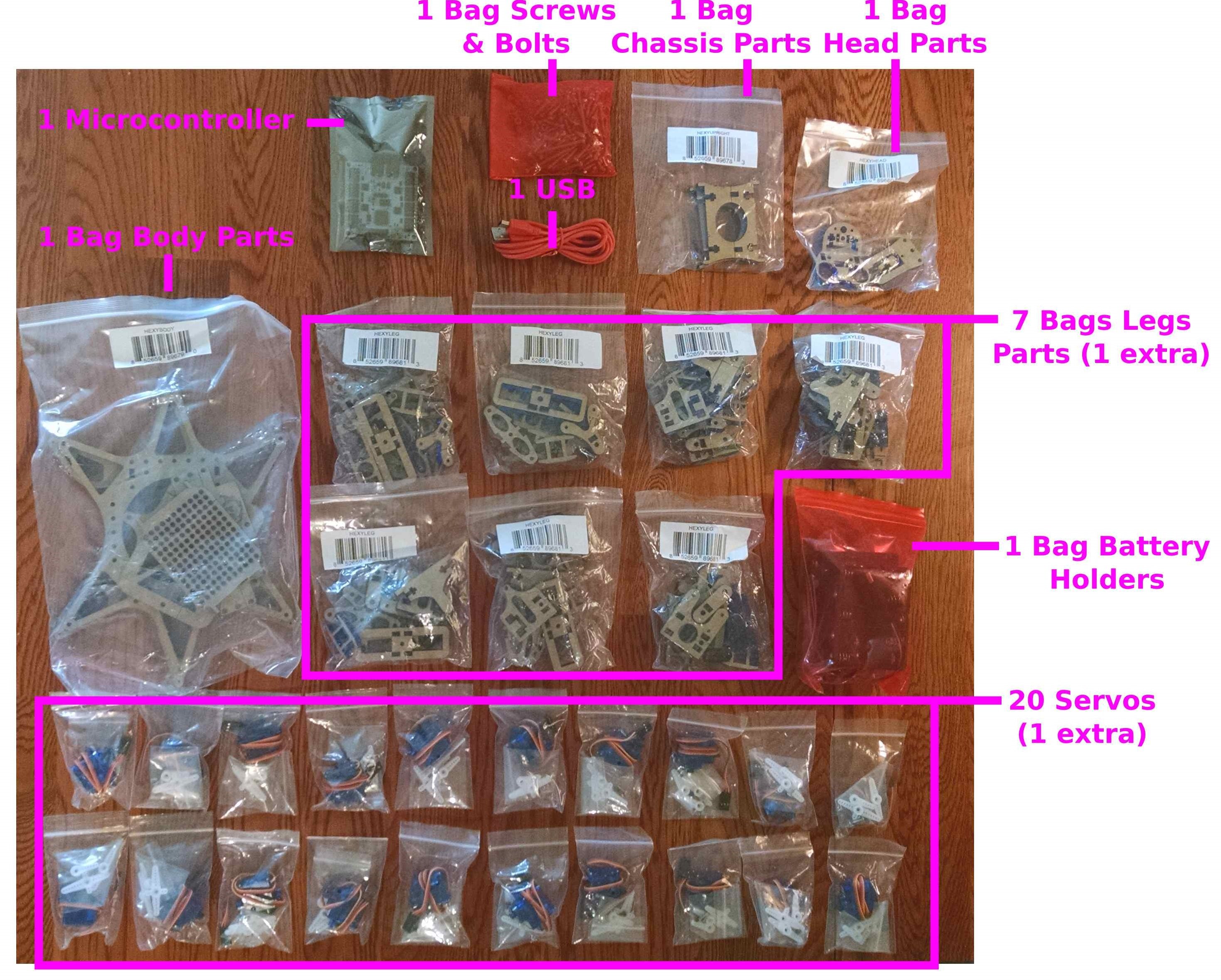
Here’s what it looks like unpacked:
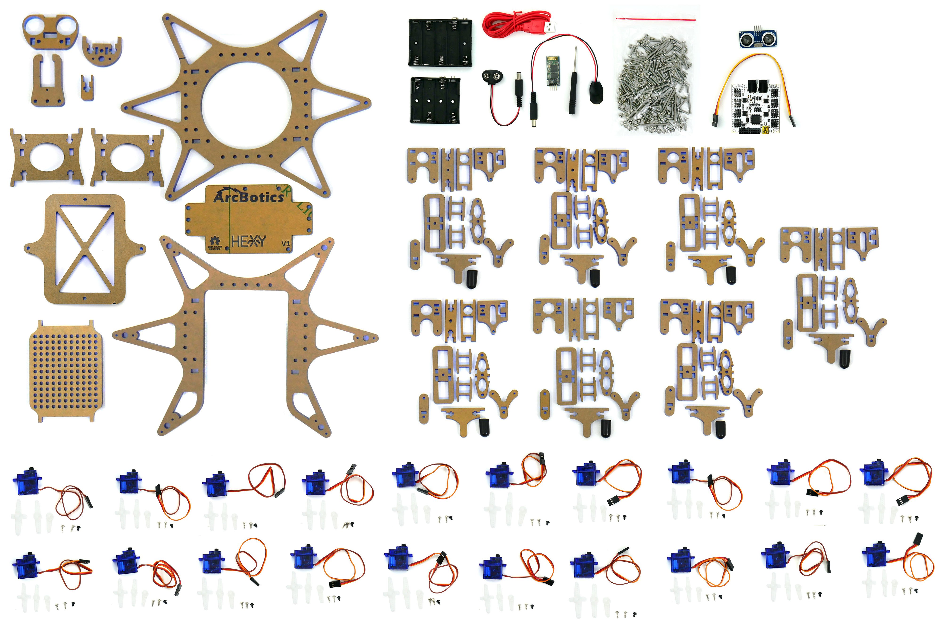
- 1 Large bag of body pieces
- 7 Small bags of leg pieces (6 legs + 1 extra)
- 1 Bag of screws/bolts/nuts
- 1 Bag of head pieces
- 1 Bag of chassis pieces
- 20 Servos (19 + 1 extra)
- 1 Bag containing a Servotor32 controller
- 1 Bag of battery holder pieces
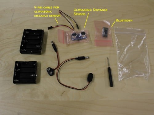
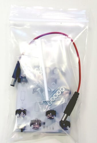
In the battery holder pieces bag, there should also be:
- 1 4xAA battery holder
- 1 5xAA battery holder
- 1 Ultrasonic distance sensor (robot’s eyes)
- 1 4pin cable for the ultrasonic distance sensor
- 1 Bluetooth serial module
- 1 long 2.1mm to 9v clip
- 1 short 2.1mm to 9v clip
- 1 small #2 Phillips screwdriver
Step 2 – Building the Legs
Time to build a leg! Each leg is constructed identically, so you are building 6 copies of the same leg. The first leg usually builds much slower than the rest will. After 6, you’ll be a pro! First, let’s make sure your first leg bag has all the pieces.
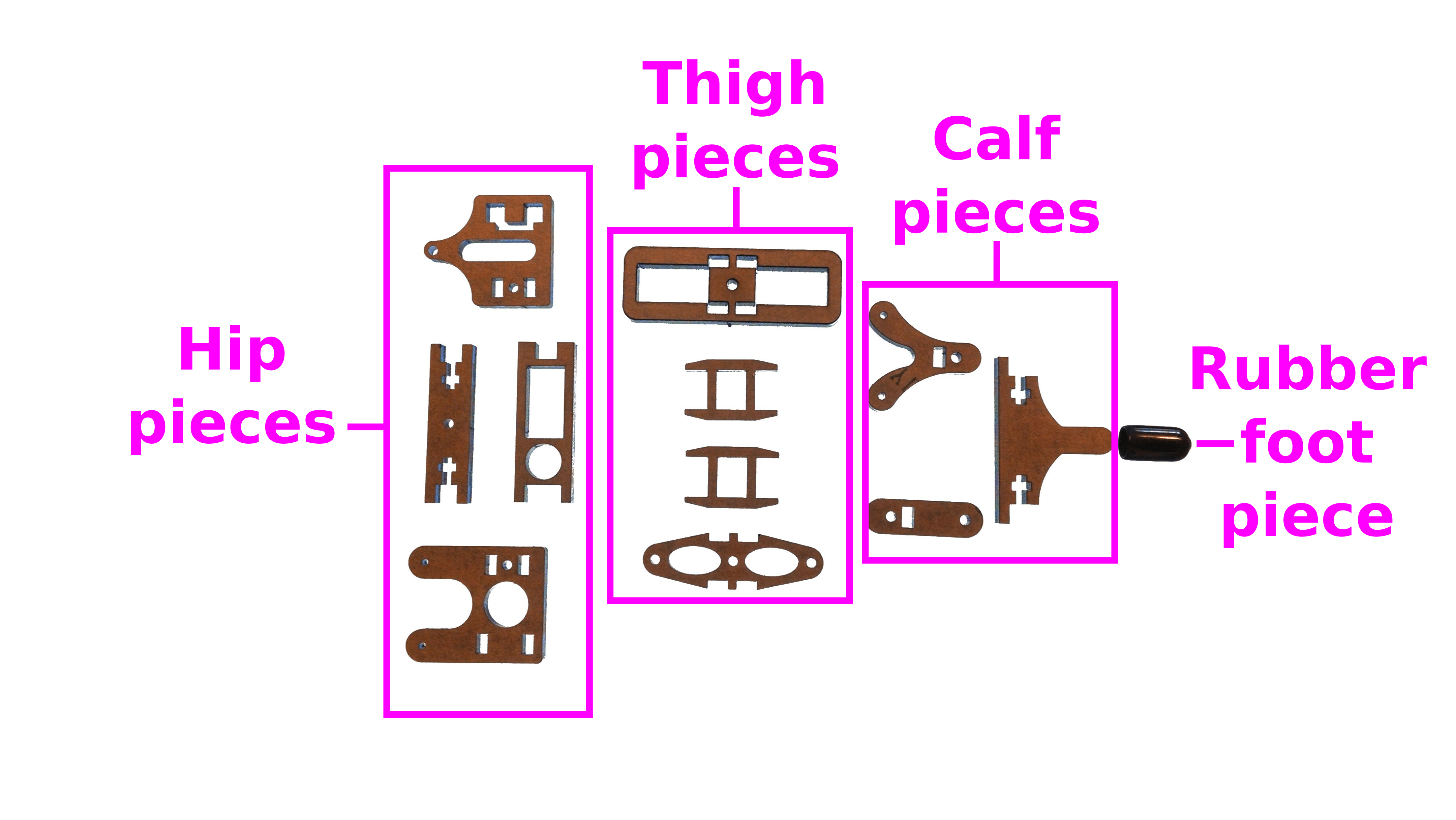
Each leg should include:
- 4 Hip pieces
- 4 Thigh pieces
- 3 Calf pieces
- 1 Rubber foot
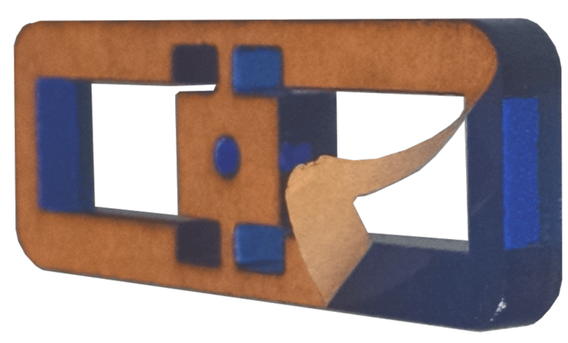
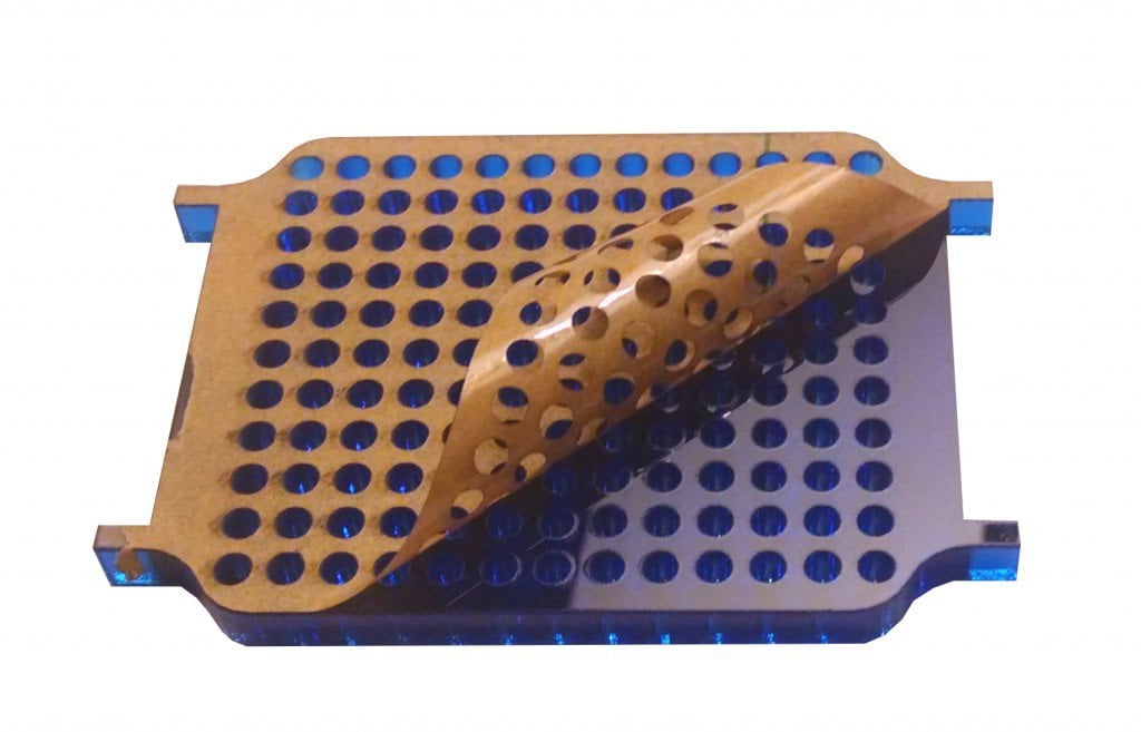
Step 2.1 – Remove the paper covering
Step 2.2 – Construct the Thigh
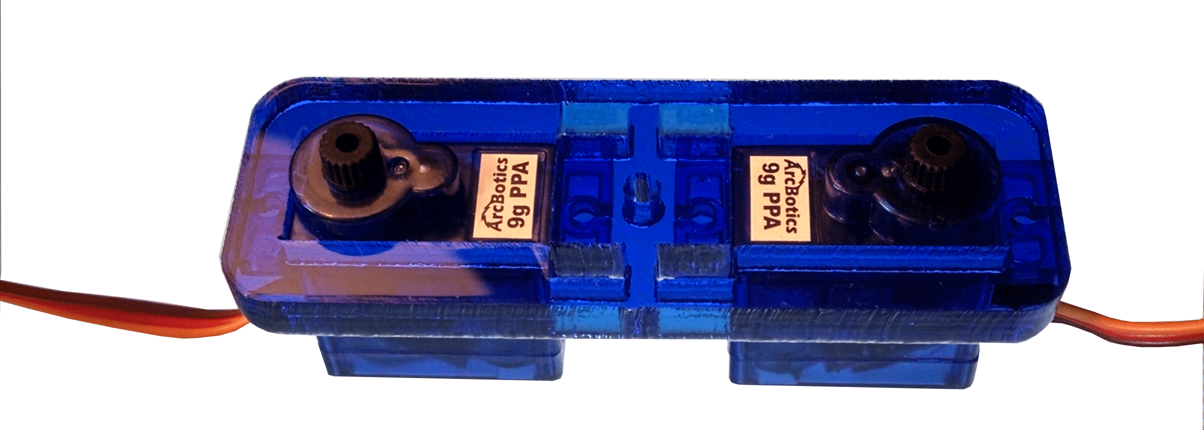
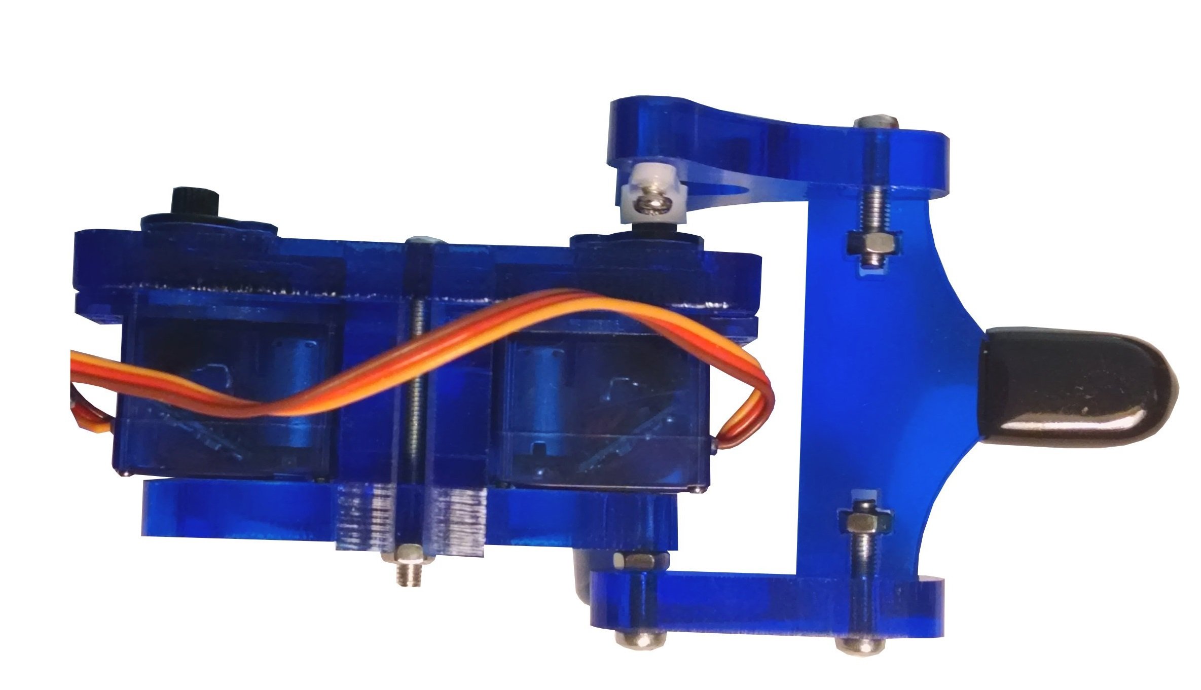
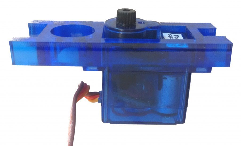
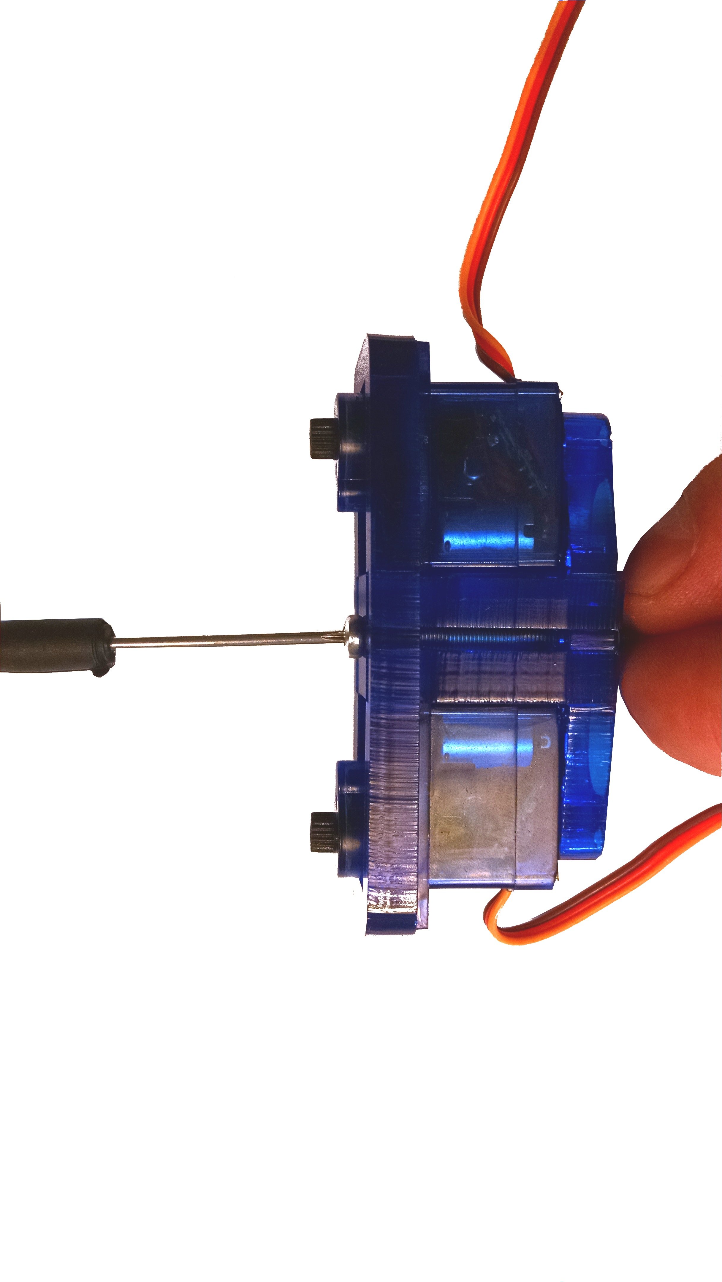
Place the servos in the left thigh piece as shown. Take note of the orientation of the servos, which have their axles and cables pointing outwards.
Attach the final calf piece with another medium bolt and nut. The leg should pivot back and forth firmly but freely lace the two middle thigh pieces (shaped like ladders) in the slots between the servos.
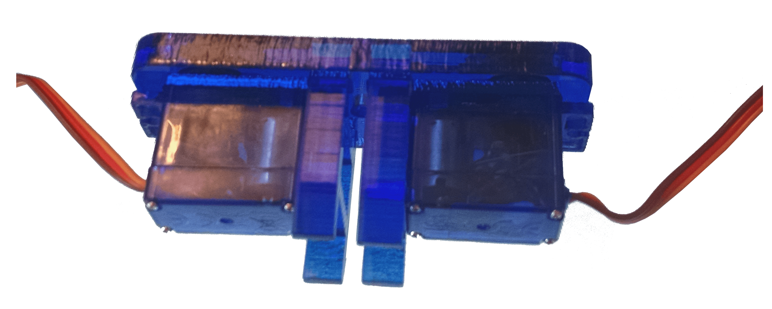
The middle thigh pieces should slip into the slots of the remaining thigh piece.
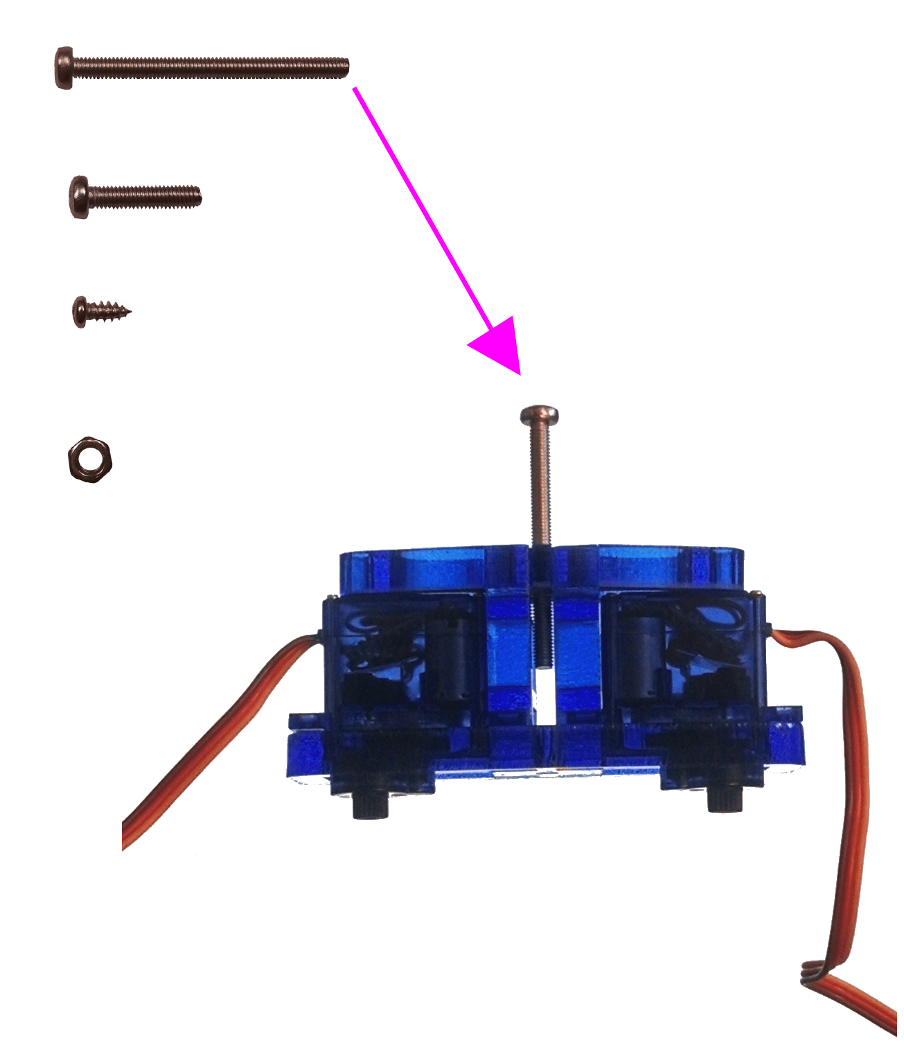
Thread one 35mm bolt (the longest one) through the hole in the center of the outer thigh pieces. Attach the nut and tighten with the screwdriver.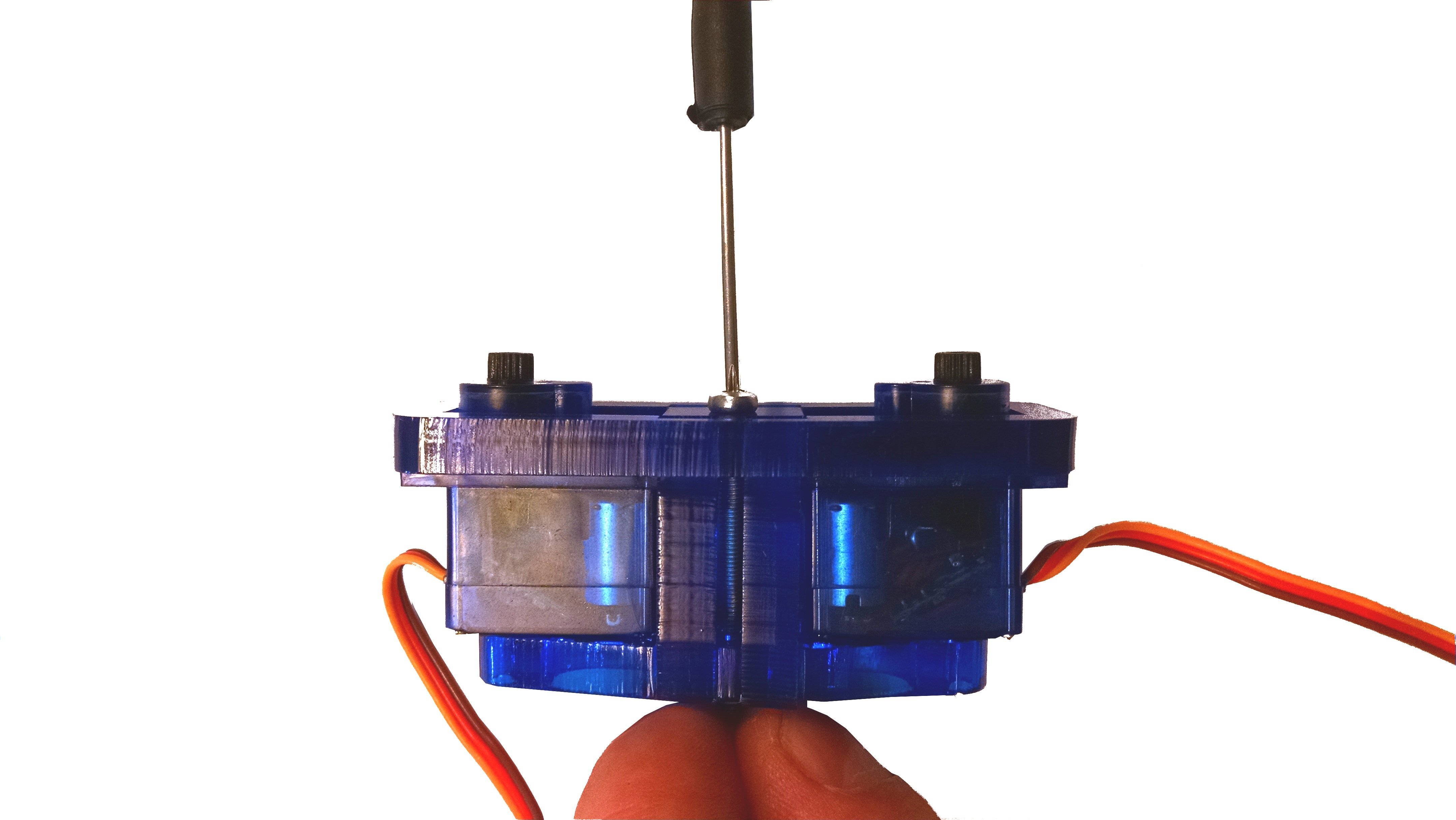
That’s it, you’ve completed your first thigh piece. Put it aside for a moment as we assemble the foot portion of this Hexy leg.
Step 2.3 – Construct the Foot
We will now move on to assembling the lower leg. Put the rubber foot onto the lower calf piece (airplane/T shaped).
The screws in the servo horn probably won’t sit completely flat on the plastic. That’s ok, as long as the servo horn is firmly attached the plastic. You don’t want your leg falling apart!
This servo horn has been attached successfully but the screws aren’t flush with the surface of the servo horn, that’s fine.
Step 2.4 – Connect the Foot to the Thigh
Using either the short or long clip, connect a battery holder to the servo plug on the controller. The controller should display a steady green light. A smaller red light should pulse dimly for a bit, flash brightly once, and then disappear.
Important: We do not recommend using alkaline batteries. We recommend using 5xAA NiMH high-capacity rechargeable NiMH or NiCads. 4xAA rechargeables is also okay. Although 4xAA batteries may sometimes work, they can also result in Hexy curling up into a ‘dead spider’ pose due to lack of current. 5xAA alkalines can fry servos. Alkalines batteries don’t work as well as NiMH, as they supply less current. See here for more info on powering Hexy. Make sure to follow the voltage guidelines printed on the board at all times, or you can damage your Servotor32 or servo motors.
With batteries plugged into the ‘servo’ plug on the controller, any servos plugged into ports 0,1,2 or 3 should automatically center (you will hear some brief whirring). If you don’t hear this whirring noise, the firmware is probably out of date and may require an update.
There is also one spare servo per kit to replace a possible faulty servo.
Plug the thigh servo into slots 0,1,2 or 3 in the controller. Make sure the brown wire is in the prong closest to the controller’s edge. Align the calf and thigh sections to be as straight as possible. Push the thigh’s servo axle into the calf’s servo horn. It will be a snug fit but do not force or twist them. Use a small screw to fasten the calf’s servo horn into the thigh’s servo. Doing this while the servo is powered and centered will ensure that the pieces are assembled centered.
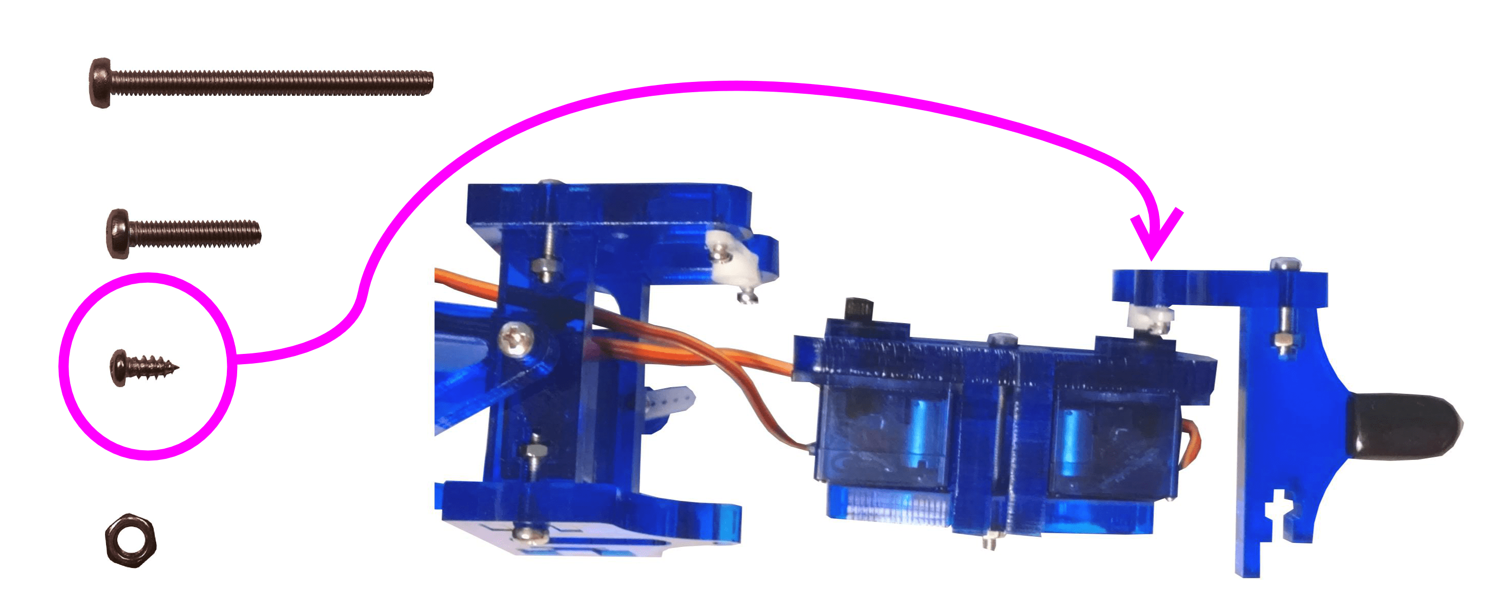
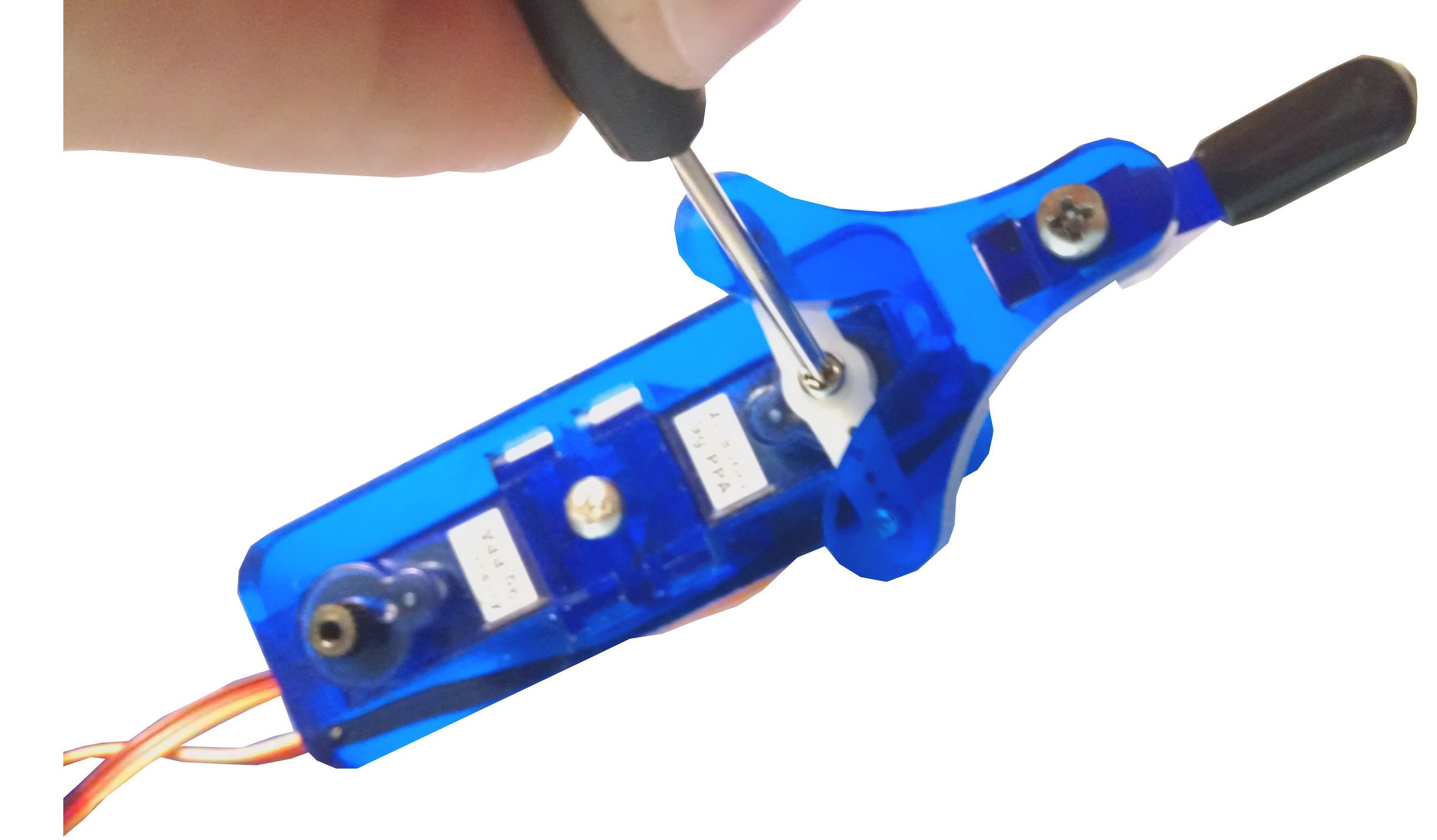
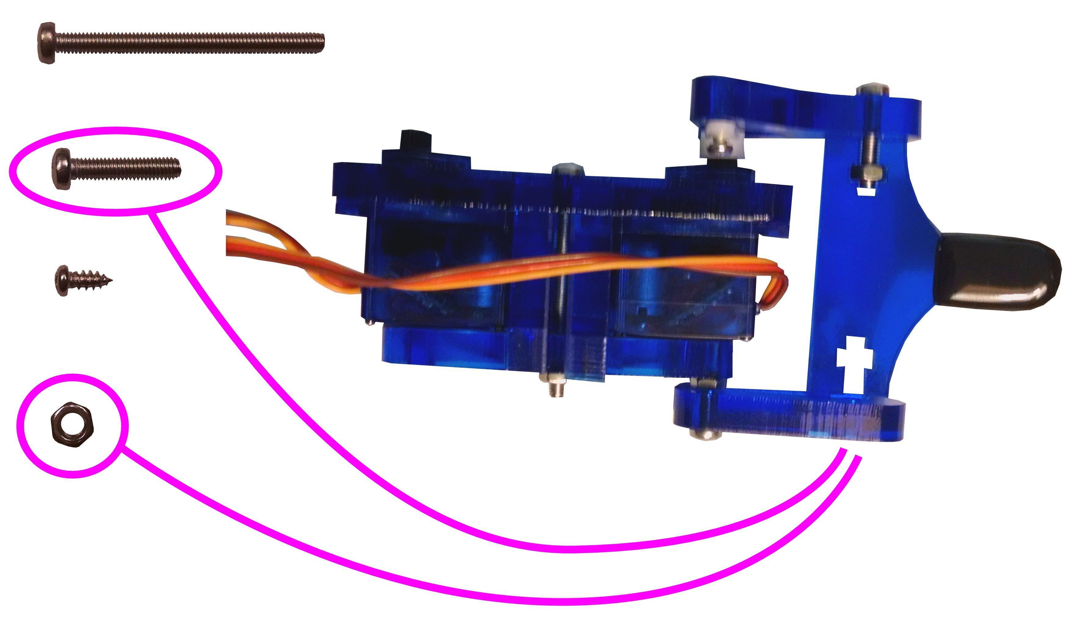
To finish securing the calf to the thigh, we will now attach the final calf piece (small rounded rectangle). Affix one medium bolt and nut as shown in the image.
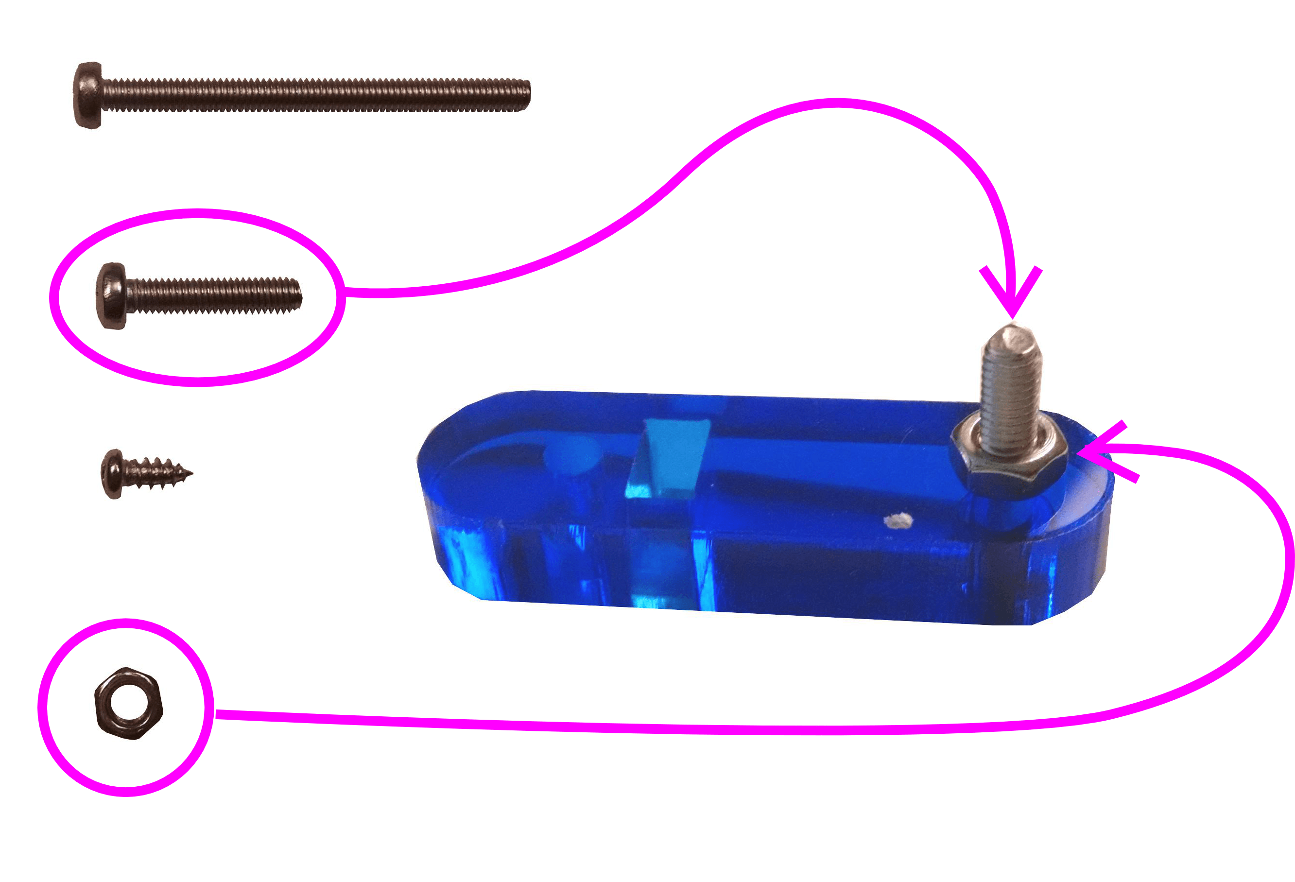
Align the final calf piece with the rest of the calf and thigh. The last bolt you just attached should fit into the thigh, and the airplane-shaped piece should fit into its slot.
Now onto the hip!
Step 2.5 – Construct the Hip
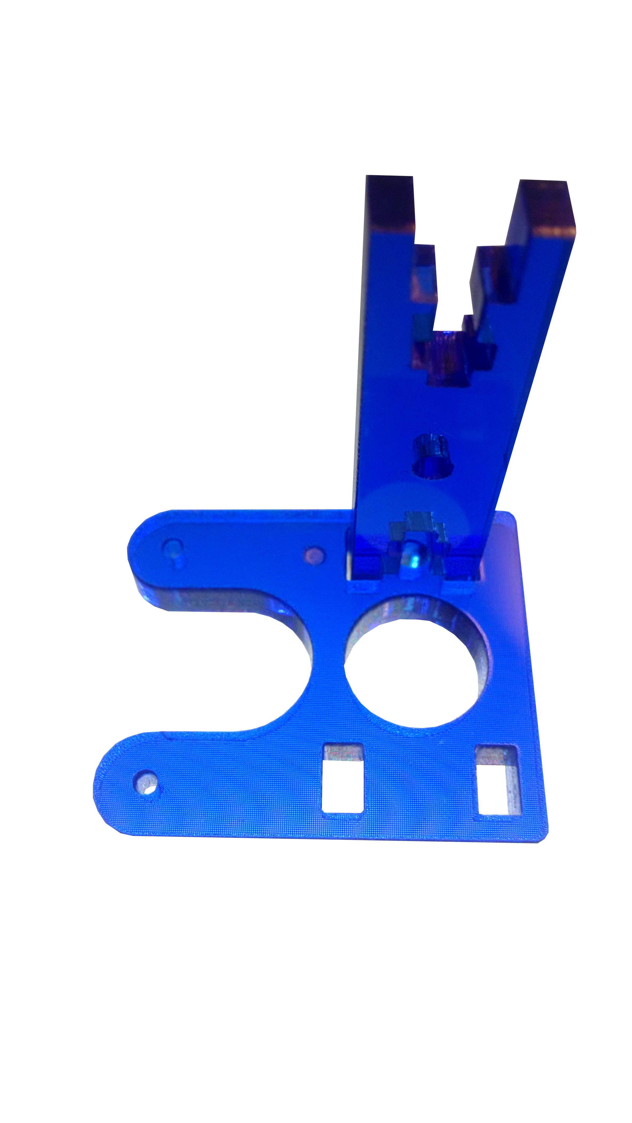
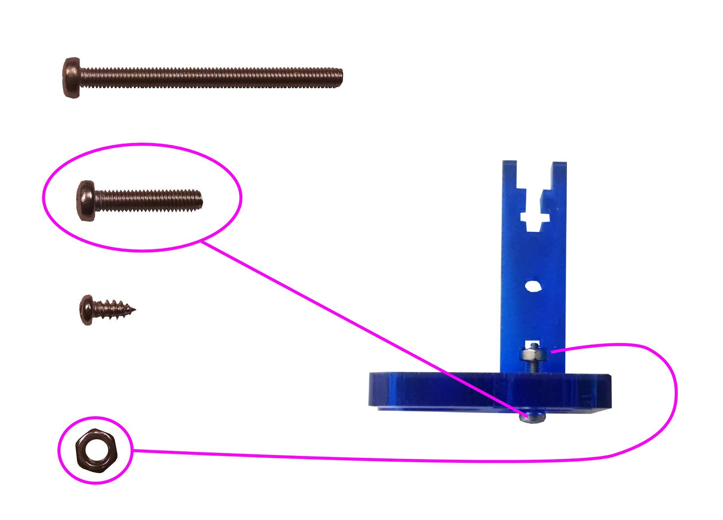
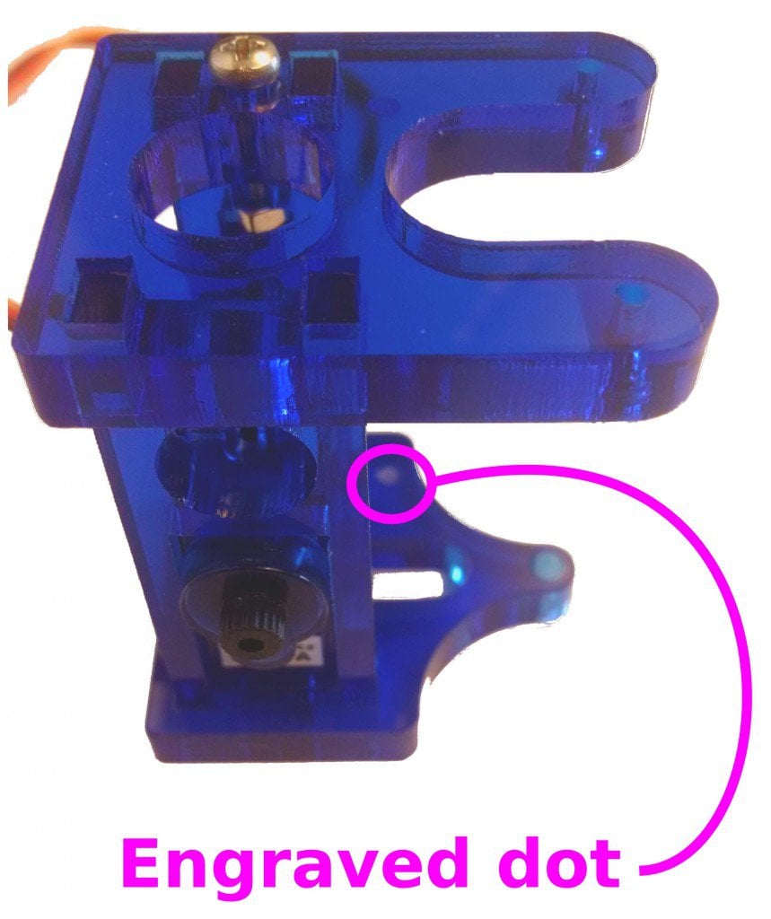
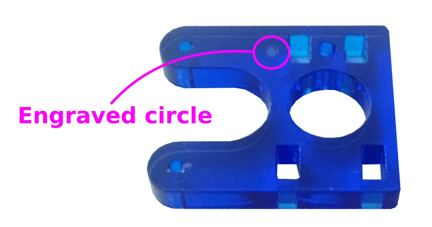
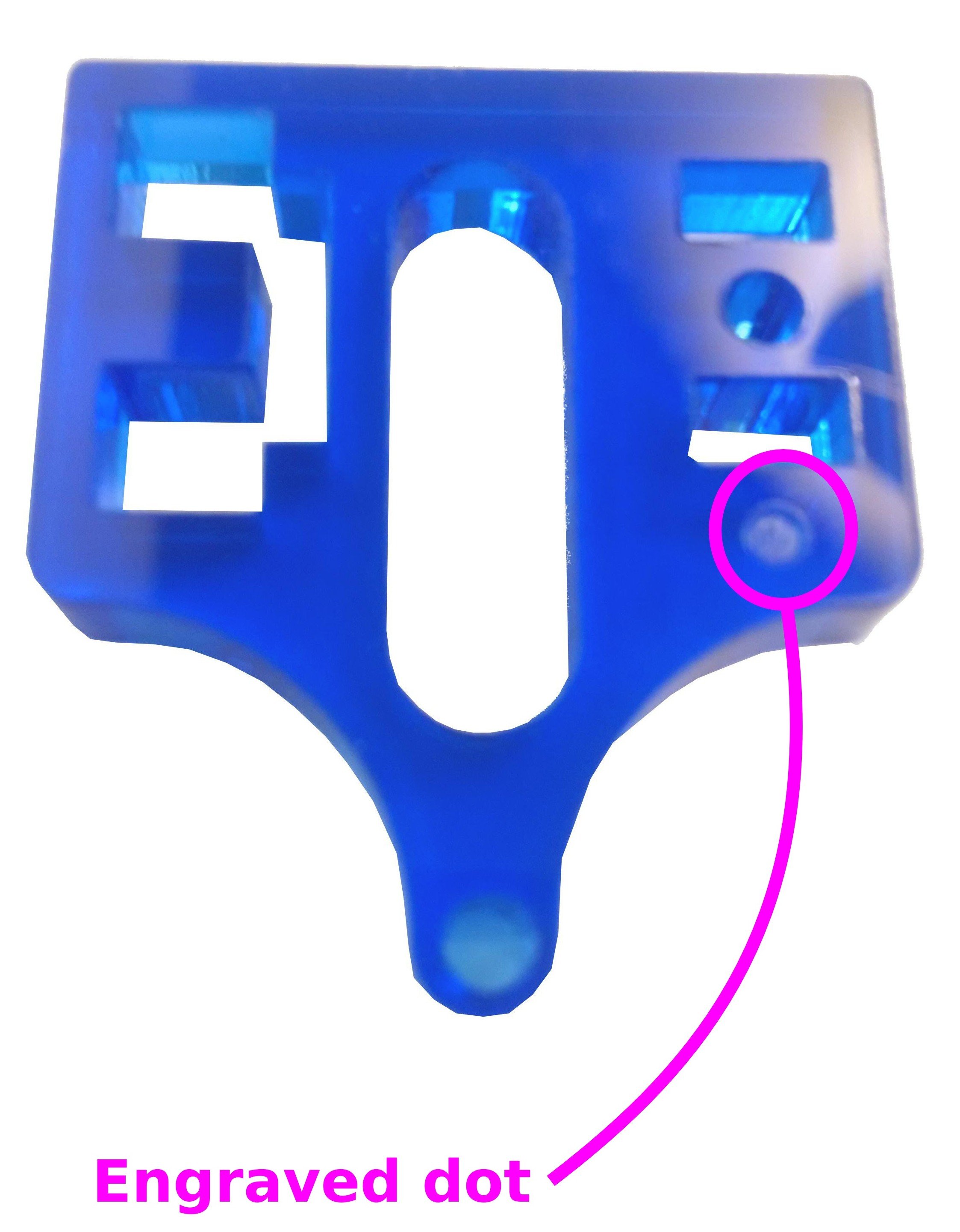
Find the U-shaped piece. The engraved circle (see image) marks the inward direction of this piece. With this engraving facing inwards, insert the clothespin shaped piece to the U-shape. Mount with a medium bolt and nut. Mount a straight servo horn onto the U-shape. This piece is mounted like the servo horn was for the feet. Note that the servo horn is also facing inwards, on the same side as the engraving, with the center hold of the servo horn facing inward.

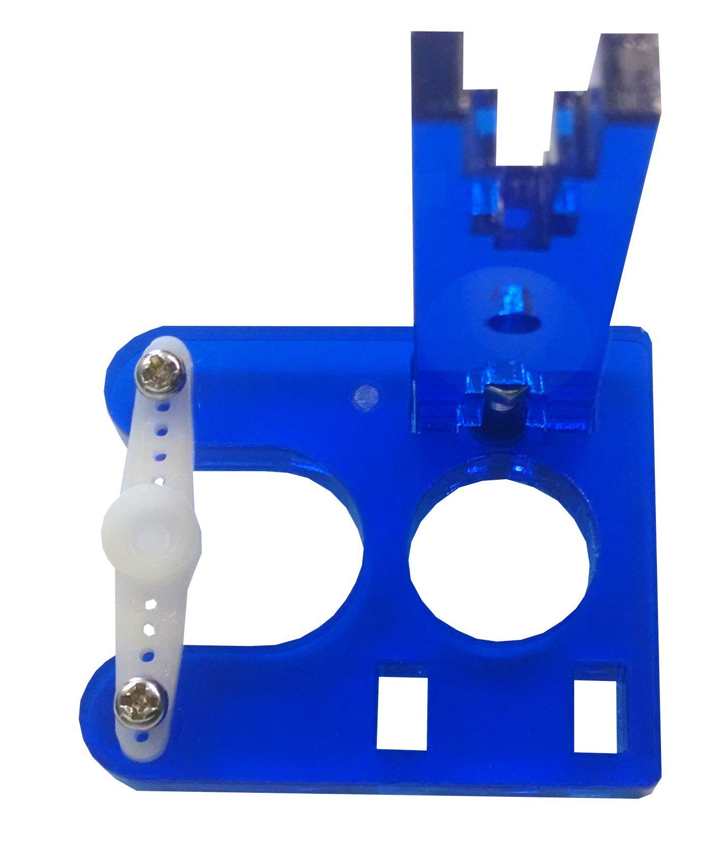
Note: the screws holding these servo horns won’t be quite as tight as they were on the foot. This is OK, because the hip is nearly completely self-contained, and the screws are more for preventing the servo horn from walking off the side than they are for biting into the material.
Put this piece aside for now. Later you’ll connect it to this next hip piece.
Step 2.6 – Connect the Hip to the Thigh


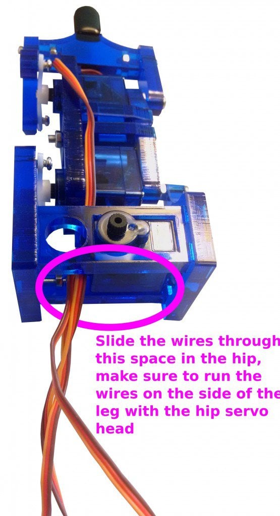
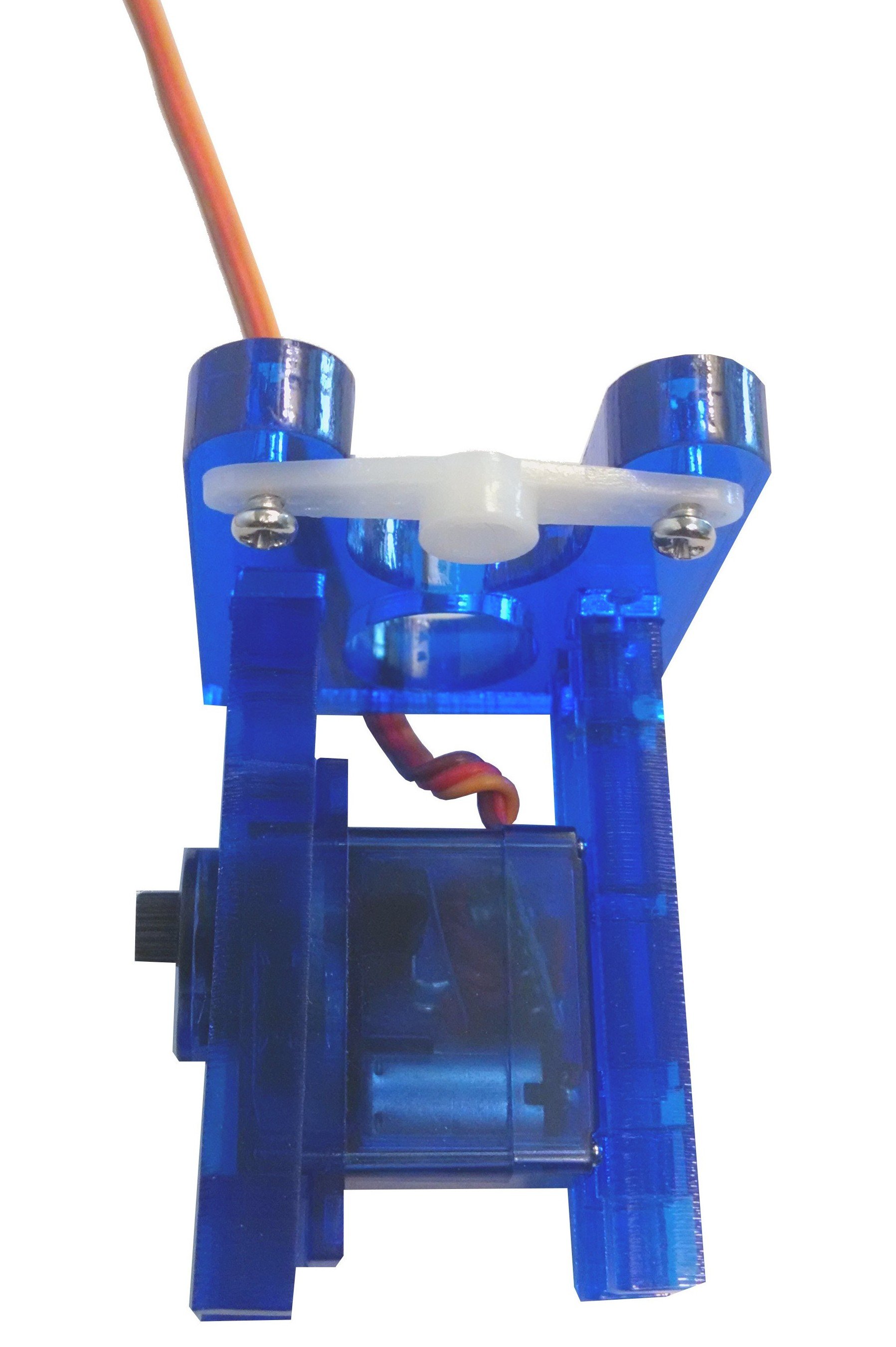
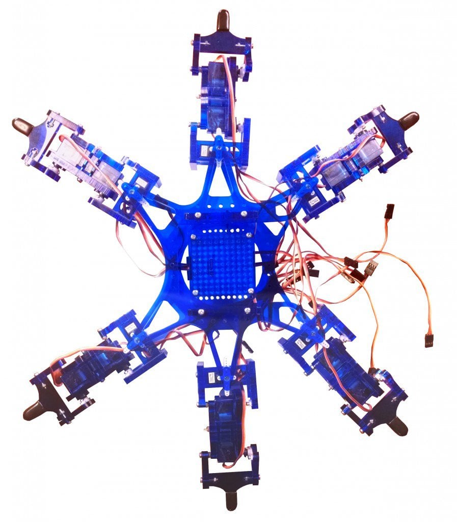
Success! An assembled leg! Thread the servo wires between the hip servo and the U-shape for a cleaner look. Build five more legs and then proceed to the next step.
Step 3.0 – Build the Main Body
Time to build the main body!
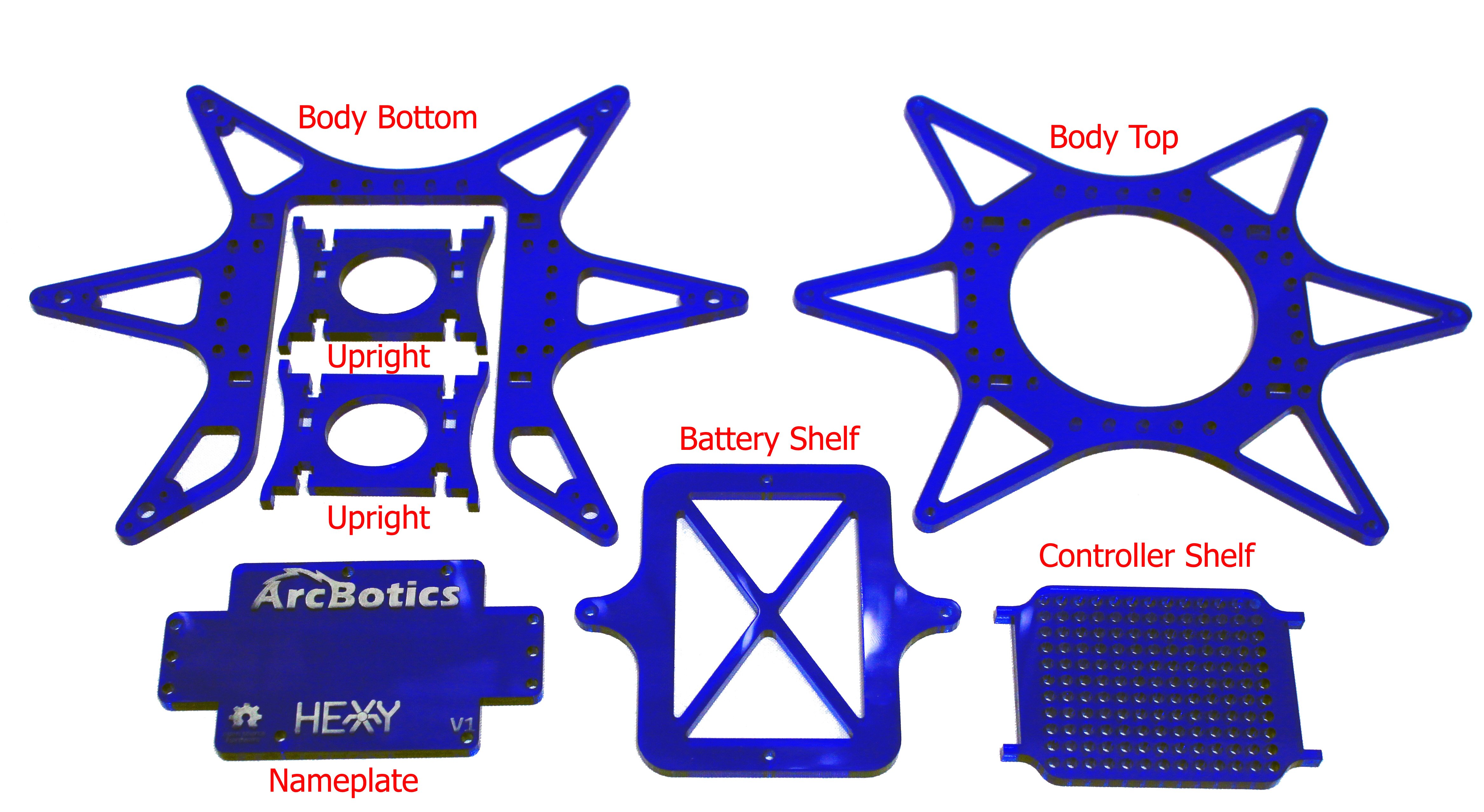
Gather the body pieces laid out in the image. You will also need machine screws and nuts, the Phillips screwdriver that shipped with the Hexy kit, 6 servo horns for the body, and 1 servo horn for the head. Peel the paper from the body pieces like you did for the legs.
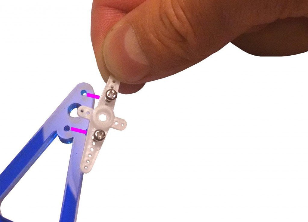
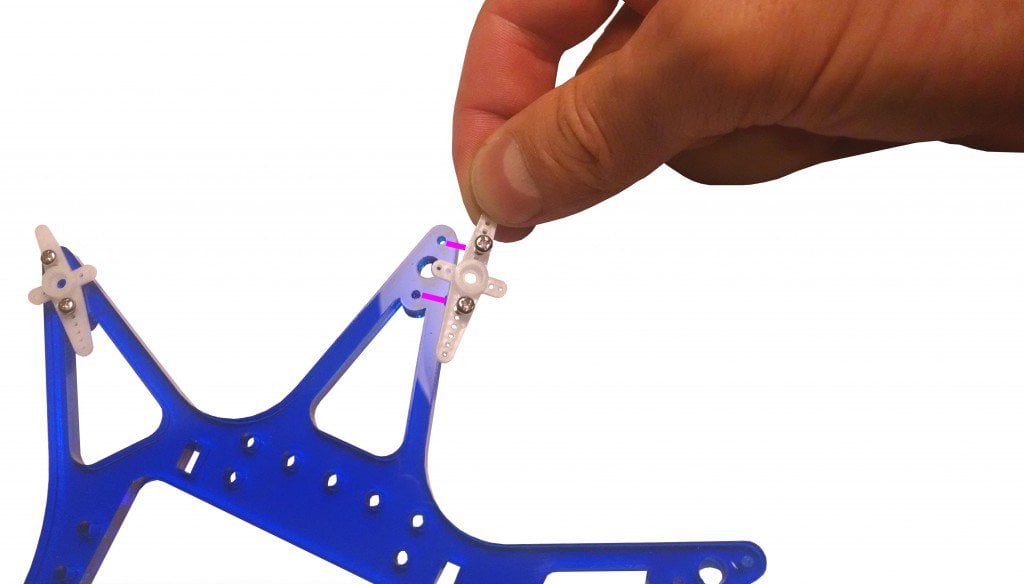
Step 3.1 – Attach the Servo Horns
Step 3.2 – Mount the Controller
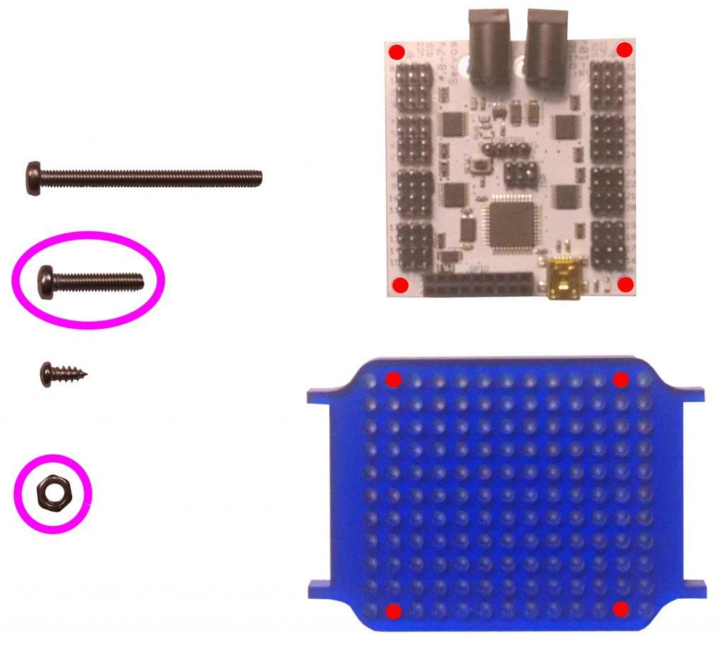
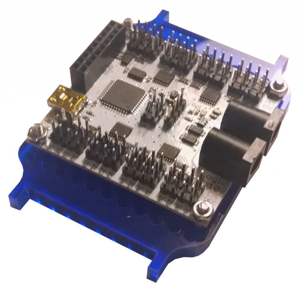
Set this completed controller shelf aside and return to the bottom body plate from earlier.
Step 3.3 – Install the Controller, Mount the Top
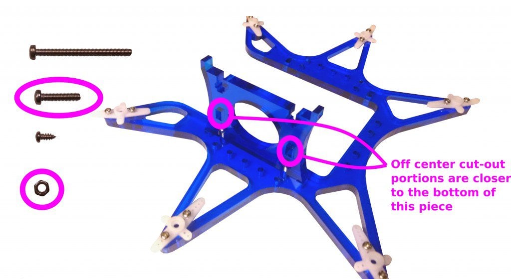
Attach the upright piece with two sets of medium screws and nuts as shown above.
Insert the second upright piece into the bottom body panel. Make sure the off-center slots are facing downwards as indicated in the previous step. However, do not screw the second upright in just yet. You will need the wiggle room to insert the controller and shelf from earlier.
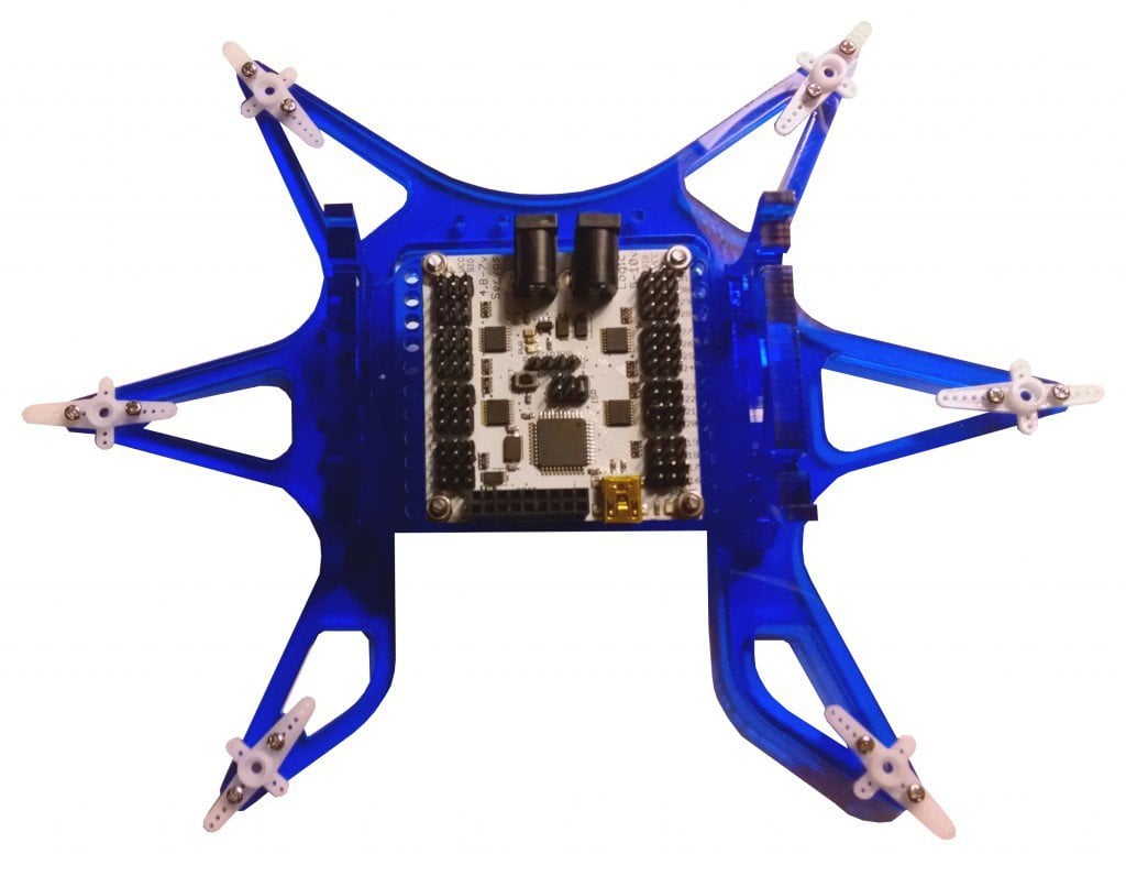
Slide the controller and its shelf between the two uprights so that it fits into their slots. Make sure the USB connector of the controller is facing the back of the robot (open end of the bottom body plate).
You can now insert two sets of medium screws and nuts into the second upright (the one you left loose in the previous step) to secure these pieces.
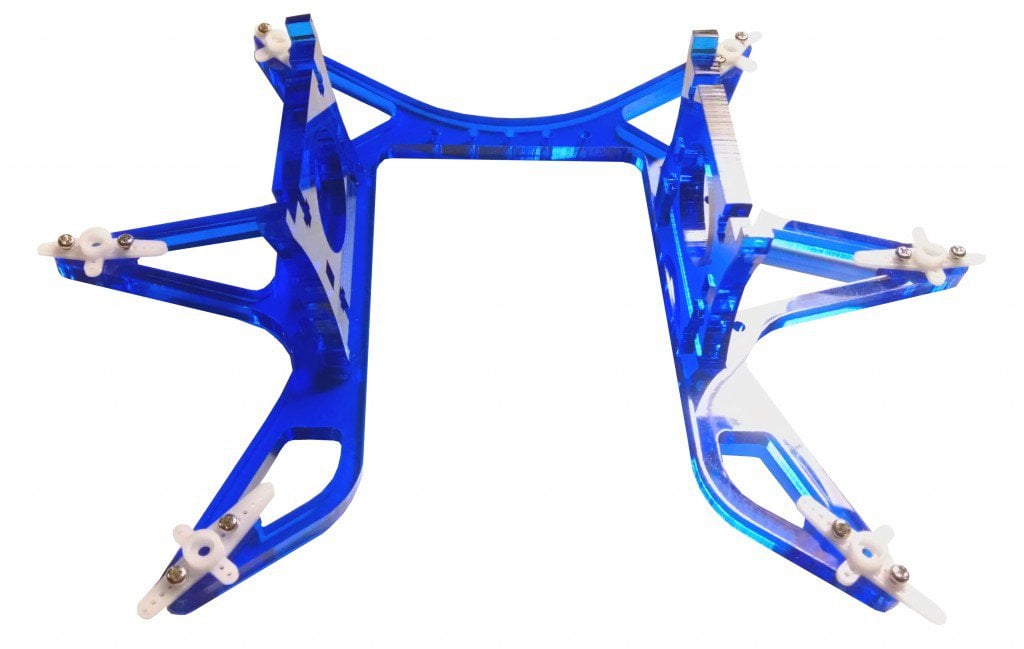
Now find the top body panel, it looks very similar to the bottom body piece. The top body panel should fit snugly on top of what you’ve assembled thus far. Attach with four sets of medium nuts and bolts as indicated in the image. The nuts will slide into the side panels that hold the controller shelf in place.
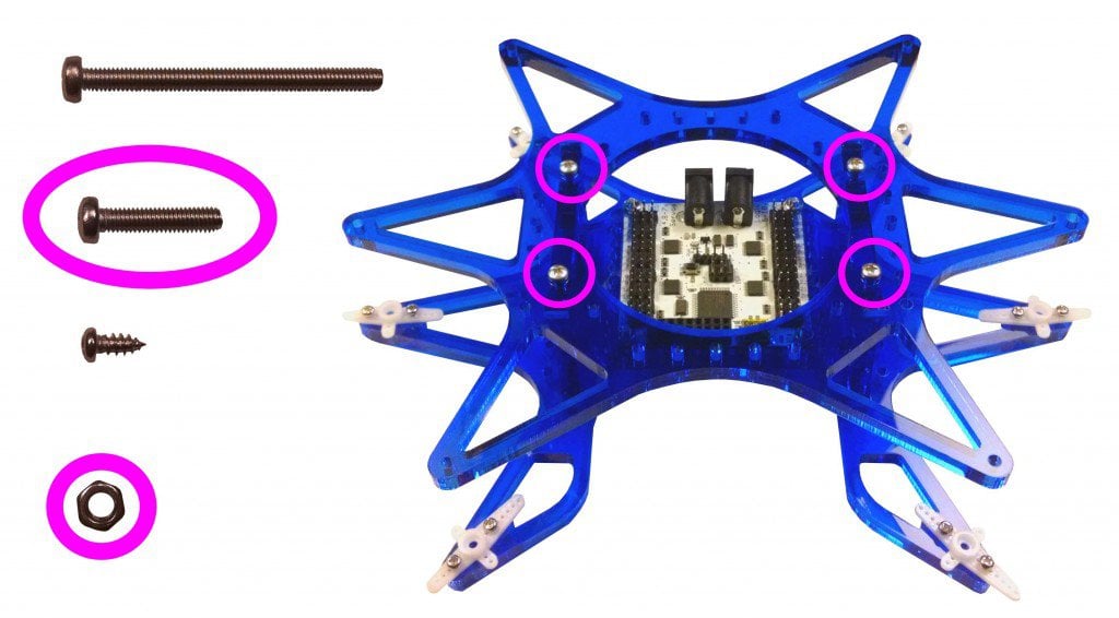
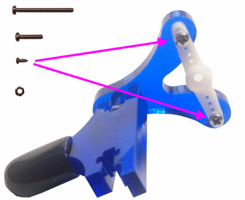
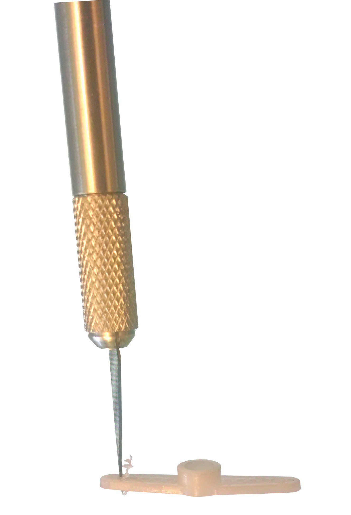
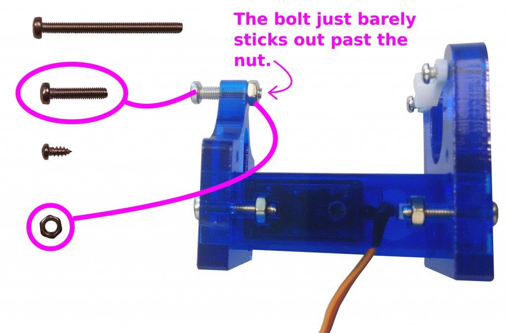
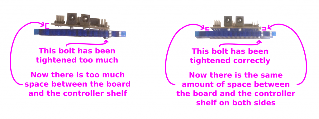
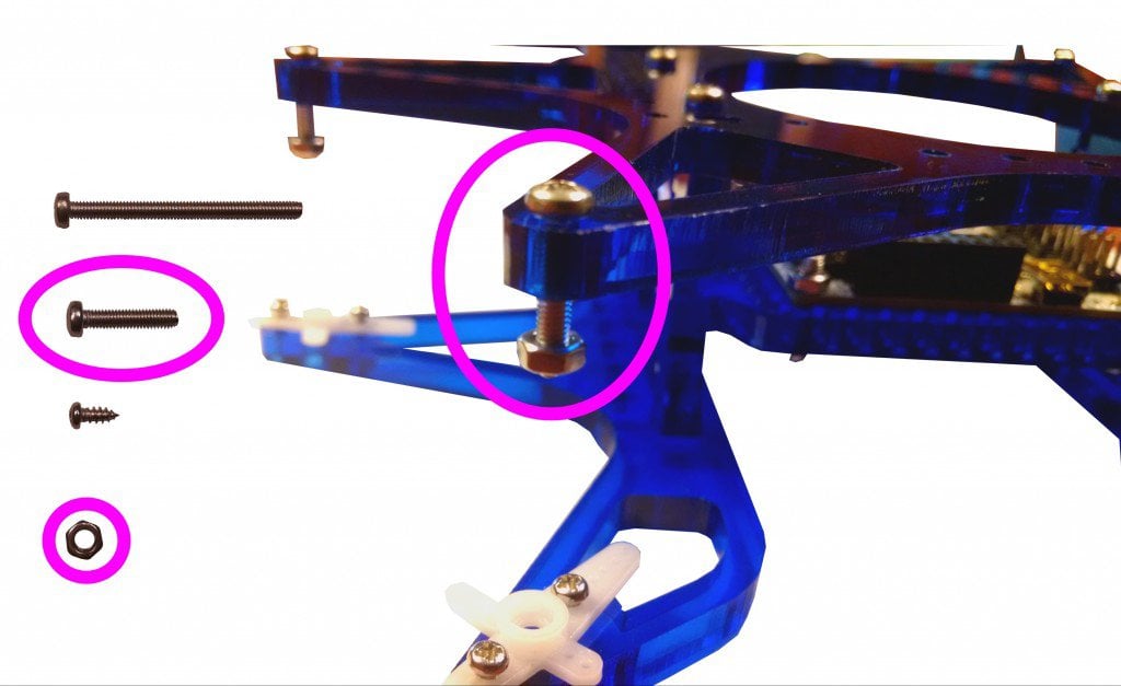
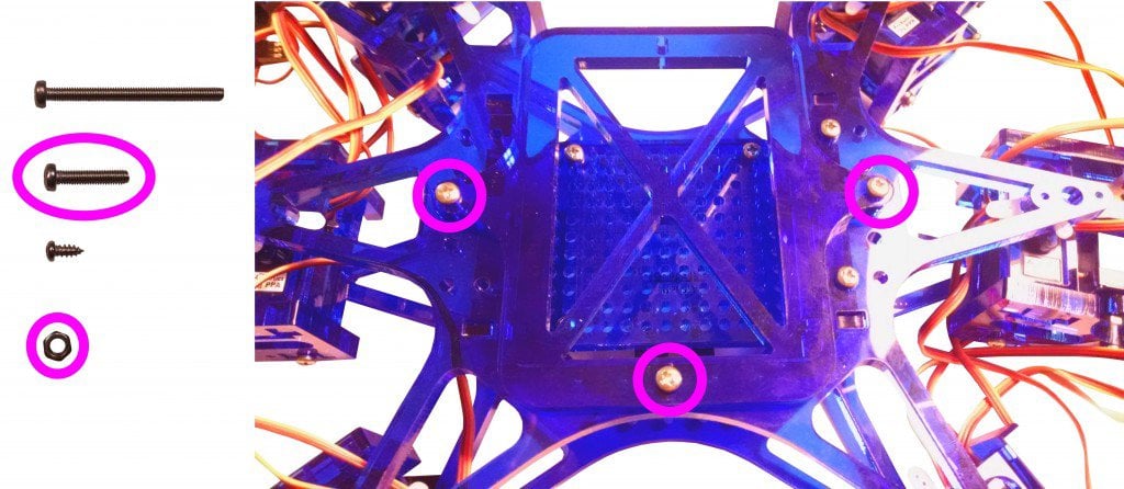
On each of the triangular points of the top body panel, you will now insert a medium bolt. Make sure it is facing downwards with the head of the bolt resting on the top of the top body panel. Then add a nut on the bottom of the bolt. Partially tighten the nut so that only the tip of the bolt protrudes beyond it. See image below for clarification.
Step 3.4 – Attach the Legs
Now it is time to attach the legs to the body!
Just as you did to center the leg joints, power up the Servo Controller board by plugging in the battery pack. Plug the hip servo into ports 0, 1, 2, or 3 on the controller. Make sure the brown wire faces outwards towards the controller’s edge. You should hear a light whirring as the servo centers.
The leg should extend straight out from the body (see dotted lines in image). As you can see the leg won’t always line up exactly with the body. That’s ok, just try to get it to fit as closely as you can. With the hip servo powered and centered, make sure its axle is facing downwards to fit into the servo horn on the bottom body plate. Push the servo axle into the servo horn. It will be a snug fit, but do not force or twist it!
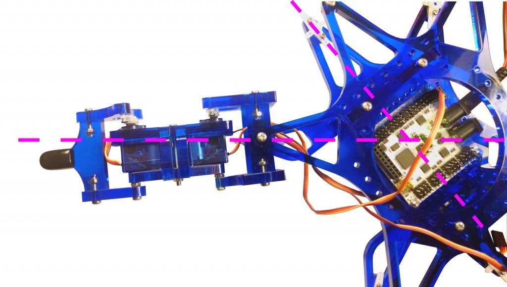
The partially tightened screw in the top body plate should be aligned with the hole in the center of the clothespin shape of the hip. Tighten this screw. Flip everything over to secure the leg to the body with a small screw on the underside of the leg.
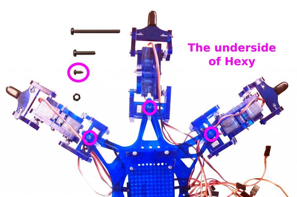
Unplug the hip servo from the controller for now. Repeat this step for the rest of the legs, making sure that you plug each servo in as you go.
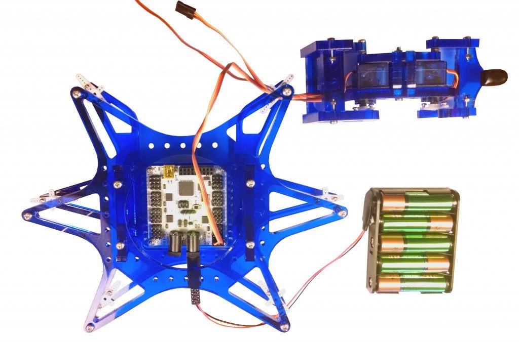
Step 3.5 – Mount the Batteries
Have black plastic battery packs? Follow the guide below.
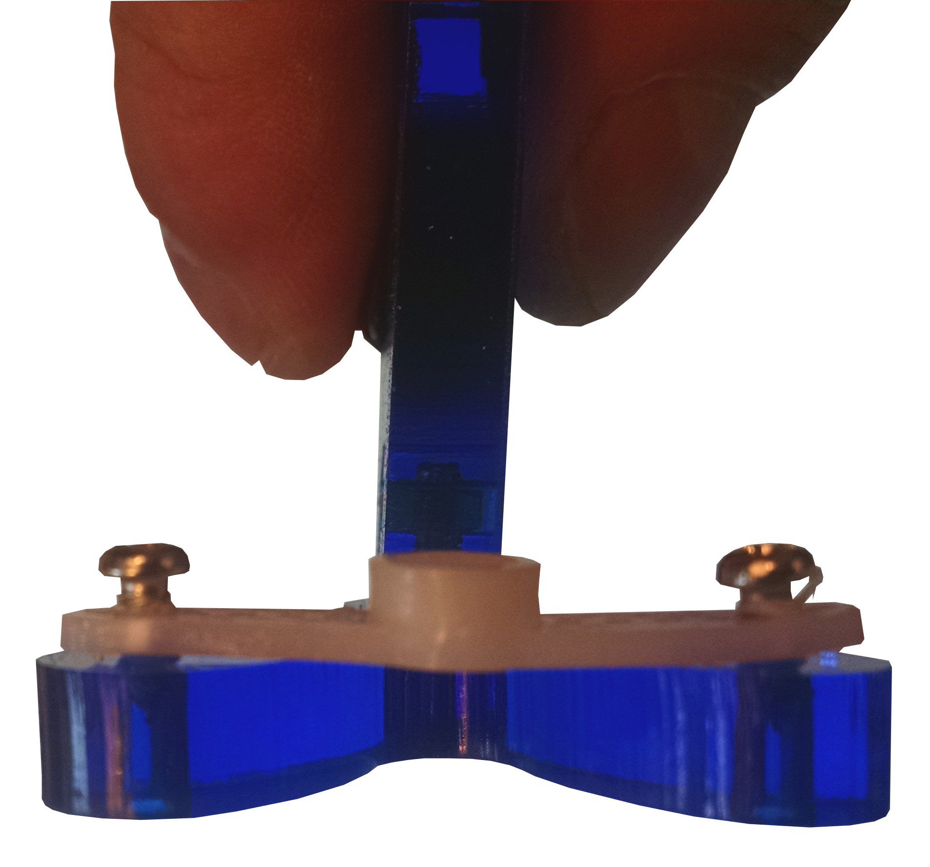
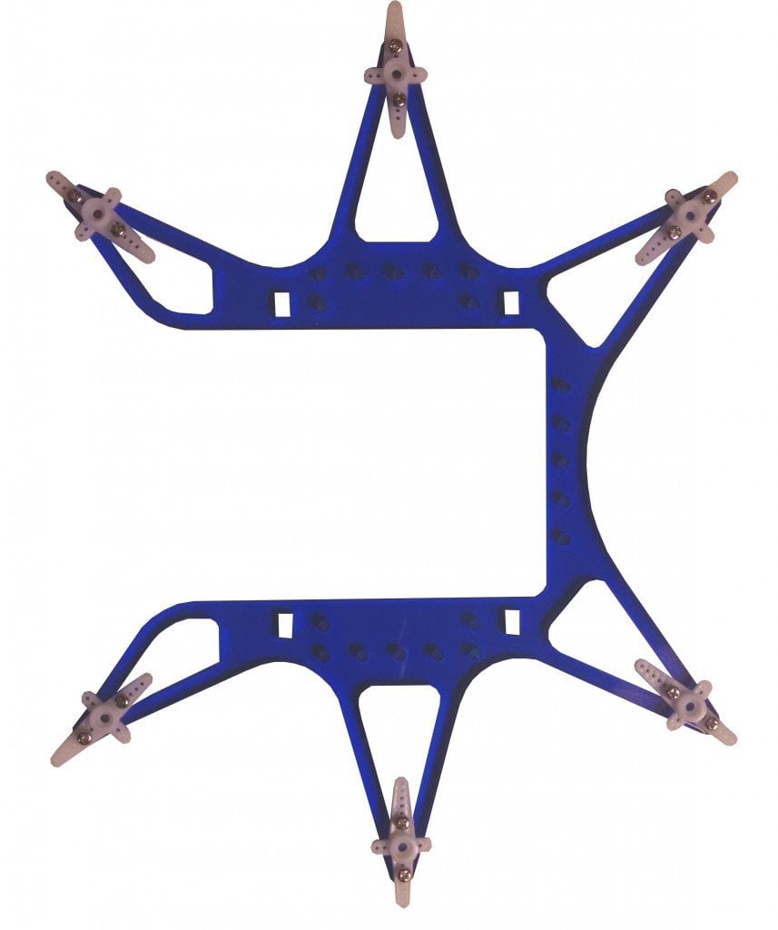
Lastly, use three pairs of medium screws and nuts to secure the battery shelf (X-shaped plate) to the underside of your robot. For this piece the position of the nuts (on the top or bottom of the battery shelf) do not matter.
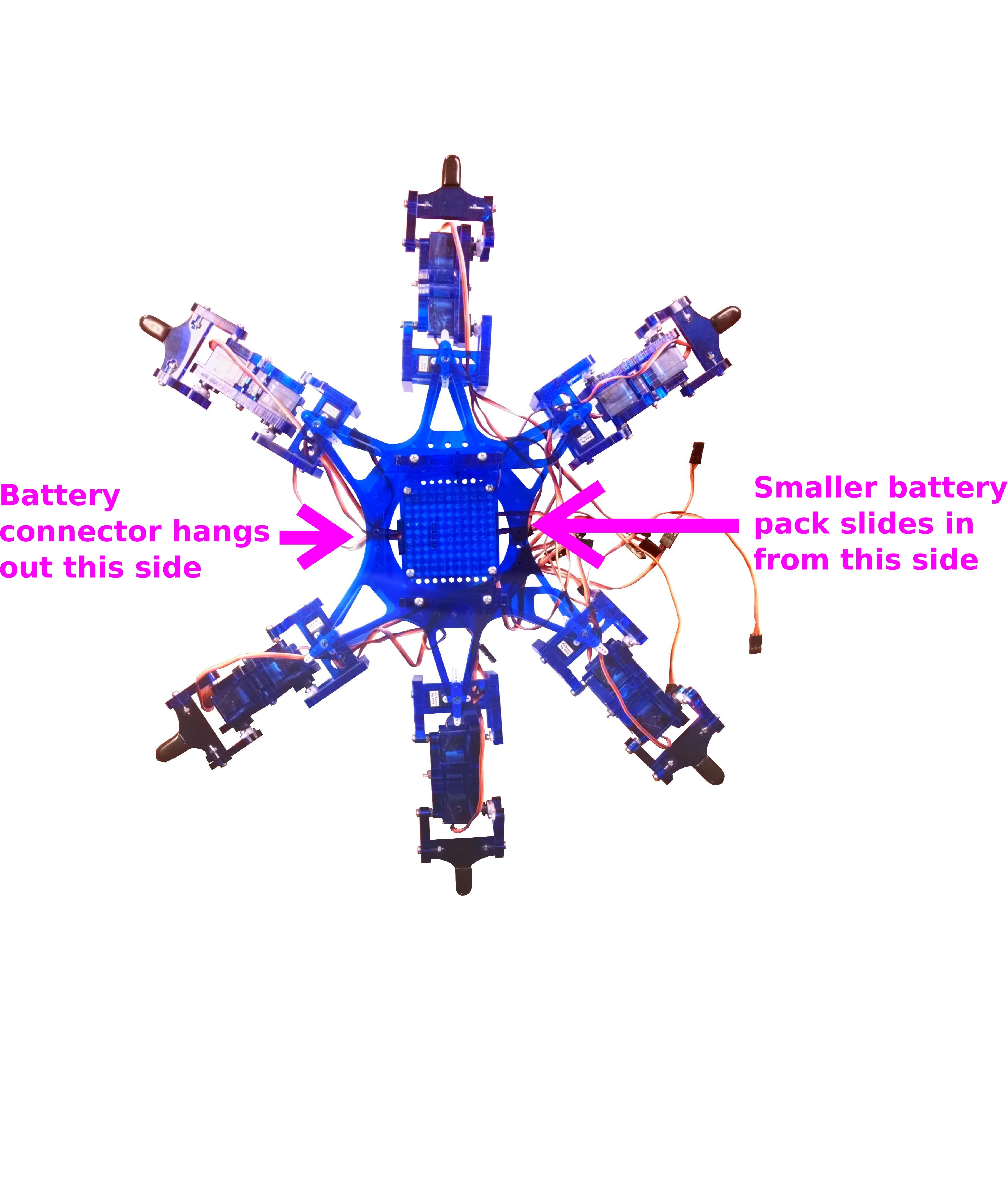
Now take the two battery packs and attach their connectors. The connectors which are black and red wires with snaps on one side and barrel jacks on the other. Make sure that you use the shorter battery connector wire for the smaller battery pack of four and the longer battery connector wire for the larger battery pack of five.
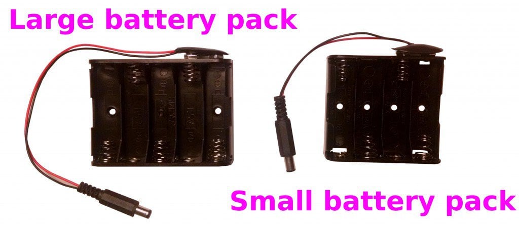
Next place your batteries into the smaller battery pack. Make sure you use the correct type of battery! If you’re not sure about this scroll up to the section that talks about batteries. (Basically, don’t use Alkaline batteries!)
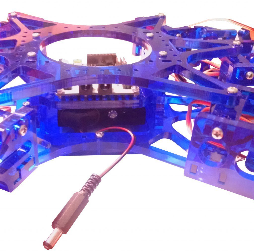
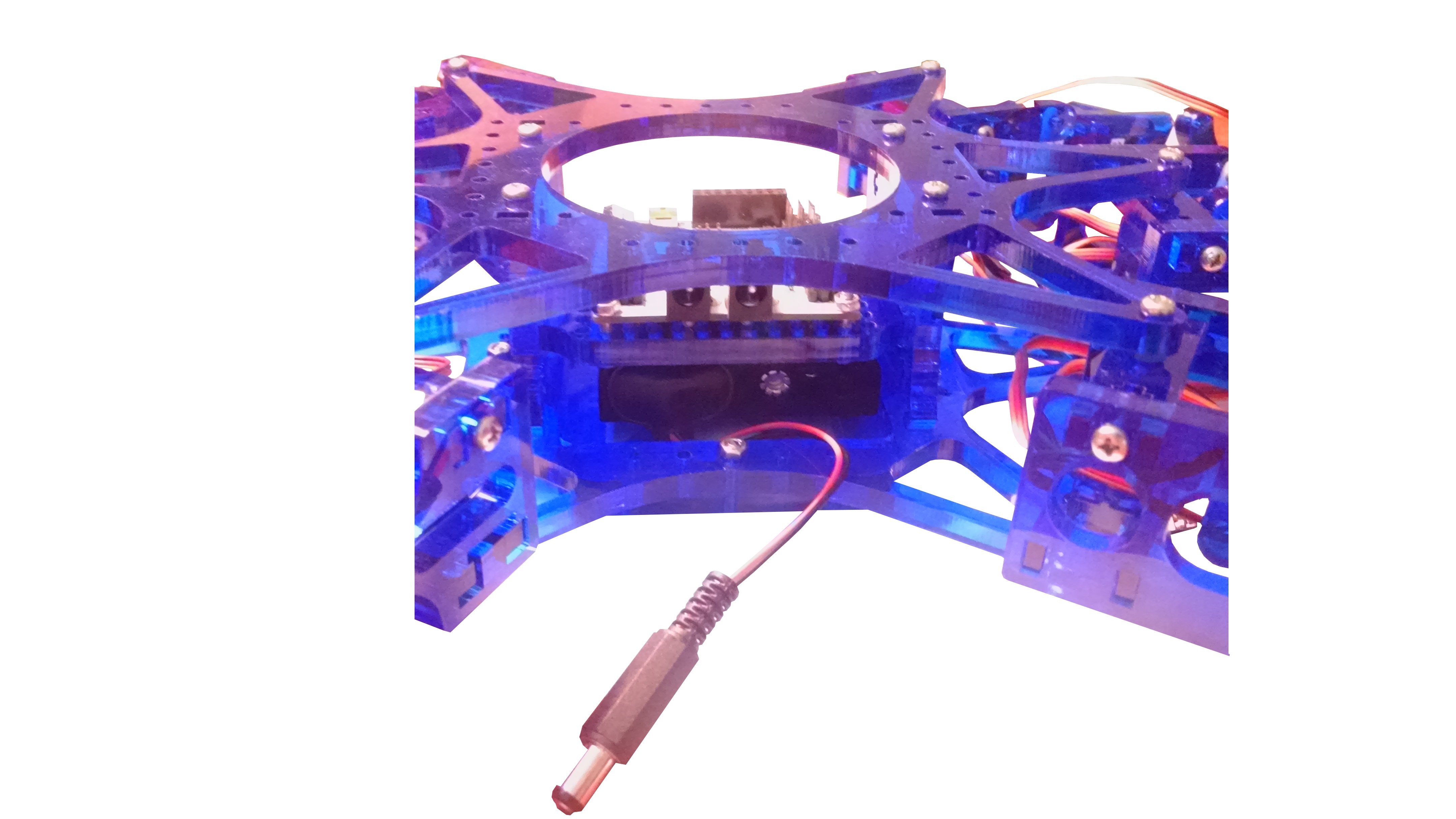
Now slide the smaller battery pack, with four batteries, into Hexy on the battery shelf you just created. You will need to slide it into Hexy from the side which has an opening in the bottom body plate. (It won’t fit easily if you try to slide it in from the other side.) Make sure that the battery connector side of the pack slides into the shelf first. This will allow you to pull the connector through the far side of the shelf and plug it into the barrel jack on the Servo Controller board, which is on the same side.

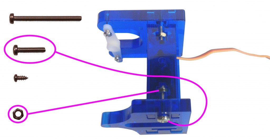
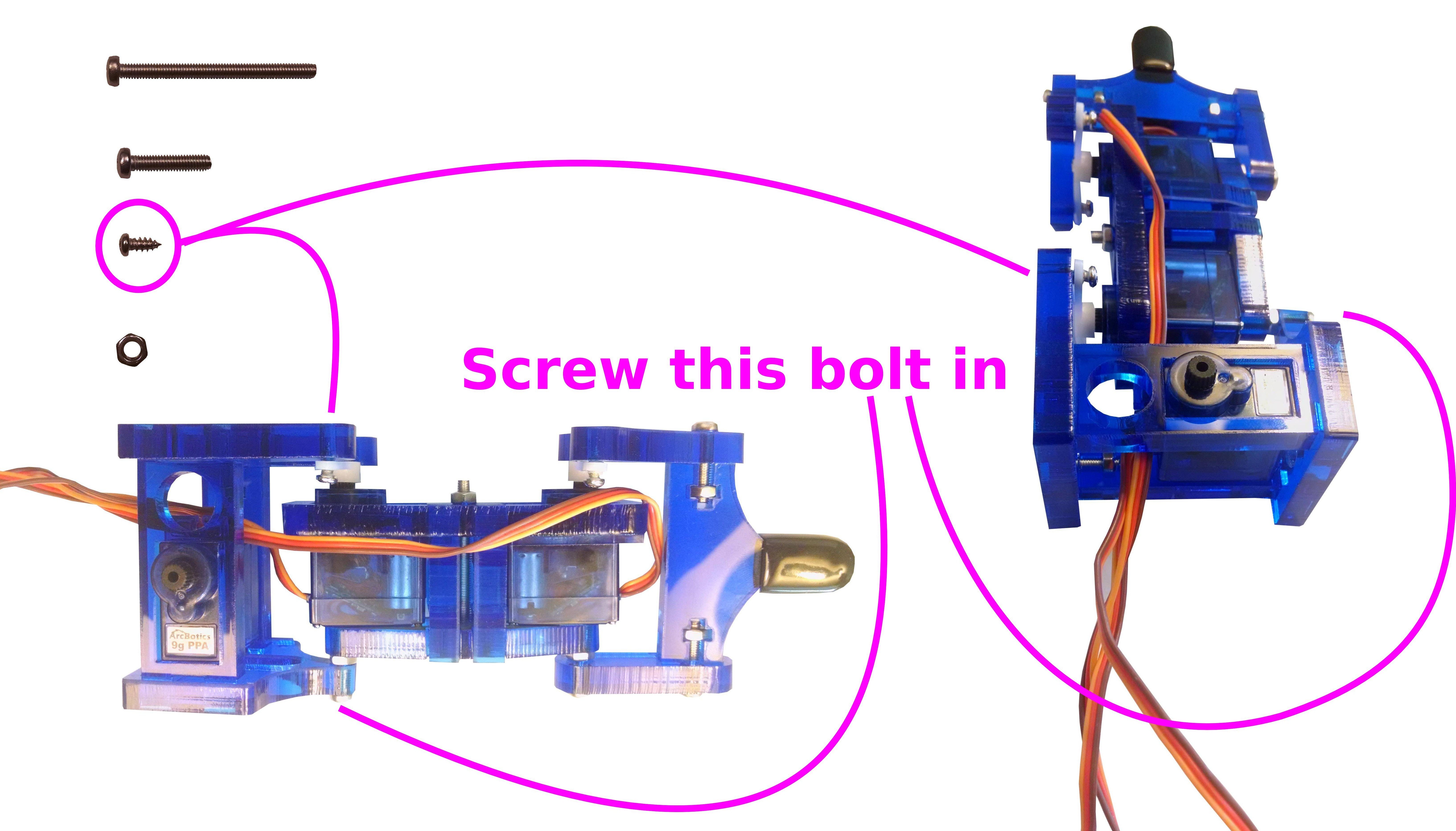
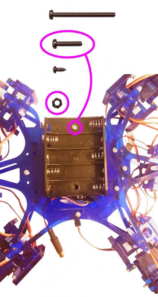
Now you will need to attach the larger battery pack, the one with five batteries to the underside of Hexy. In order to do this you will need to attach the battery pack without any batteries in it at first. You will use just one medium sized bolt and nut to attach the battery pack.
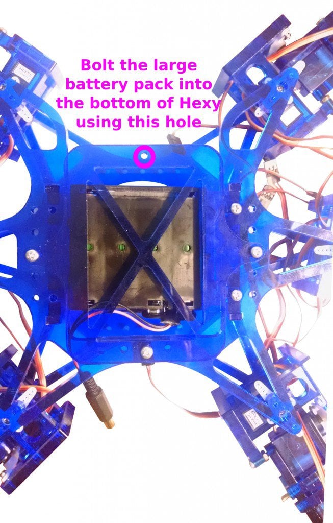
Make sure that you place the bolt through the battery pack and Hexy’s battery shelf so that the head of the bolt is on the same side as the battery pack. Otherwise the batteries will not fit into the battery pack since the nut would be in the way. The orientation of the larger battery pack does not matter since the connector is long enough to reach the Servo Controller board no matter how you attach the pack.
Put Hexy’s body aside to assemble the head next.
Step 3.6 – Attach the Head
Time to build the head!
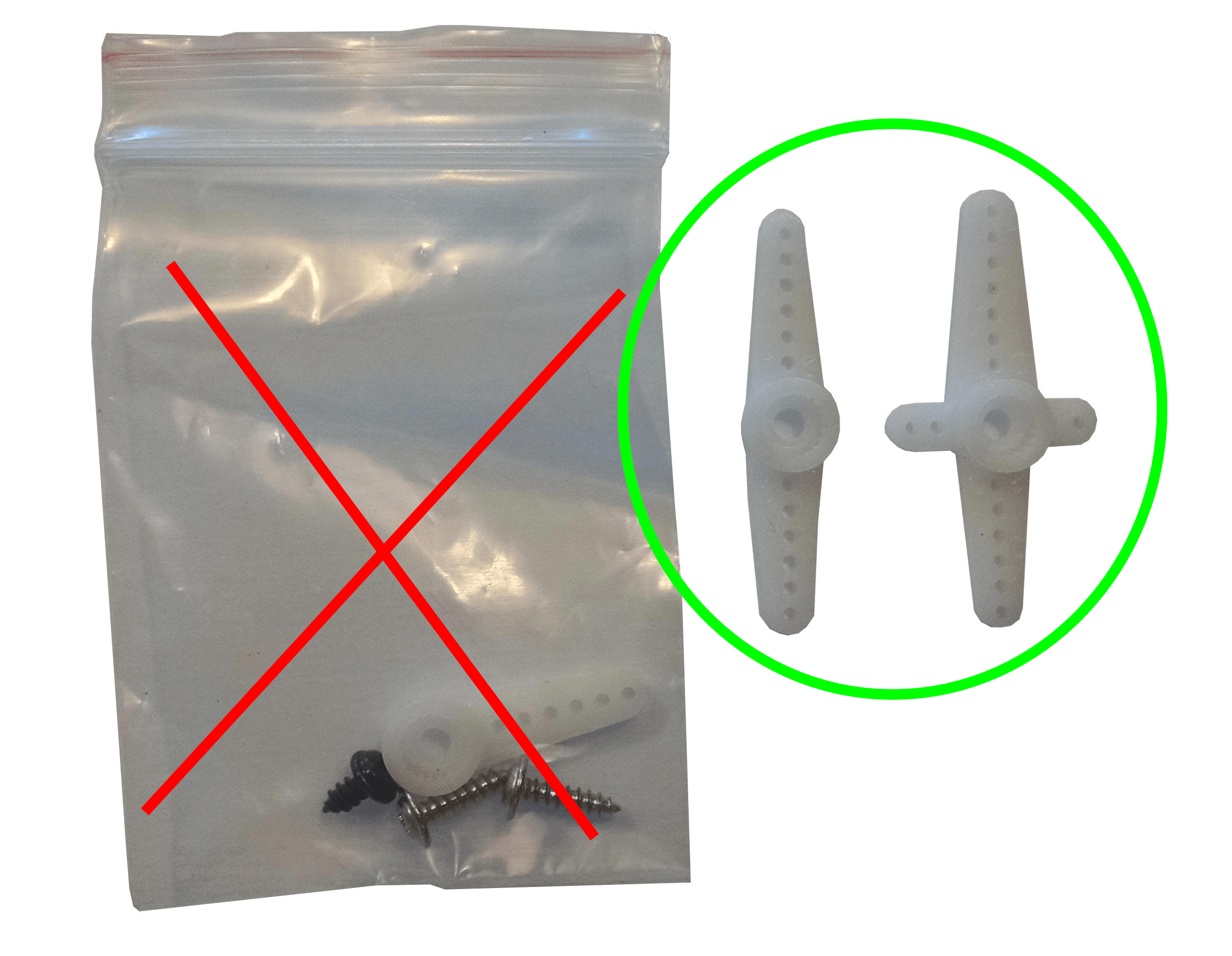
You will need one servo, one servo horn, the ultrasonic distance sensor (from the miscellaneous bag), and four pieces from the body bag (refer to image) in order to complete the head. Peel off the protective paper.
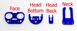
Take the ‘head back’ and insert it into the slots of the semicircular ‘head bottom’ piece, as shown in the image. Fasten with a medium bolt and nut.
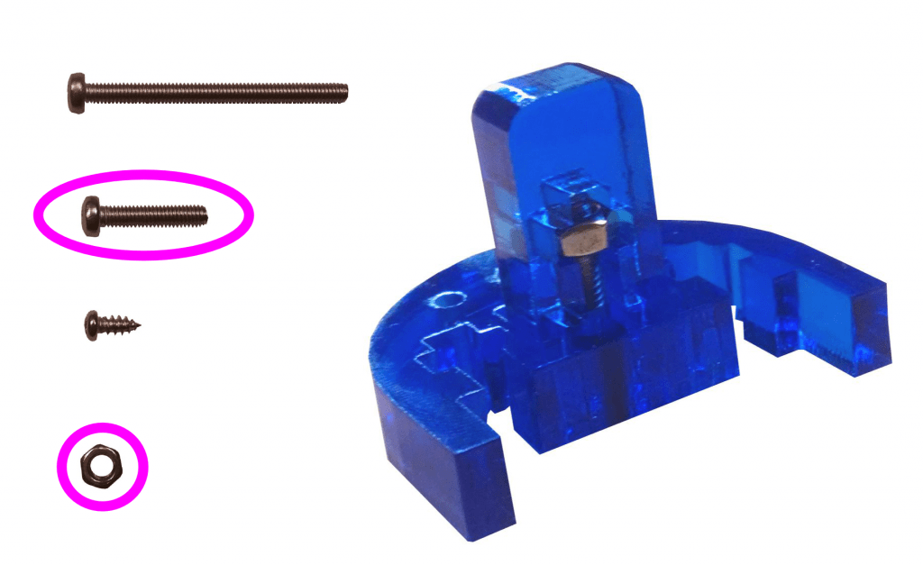
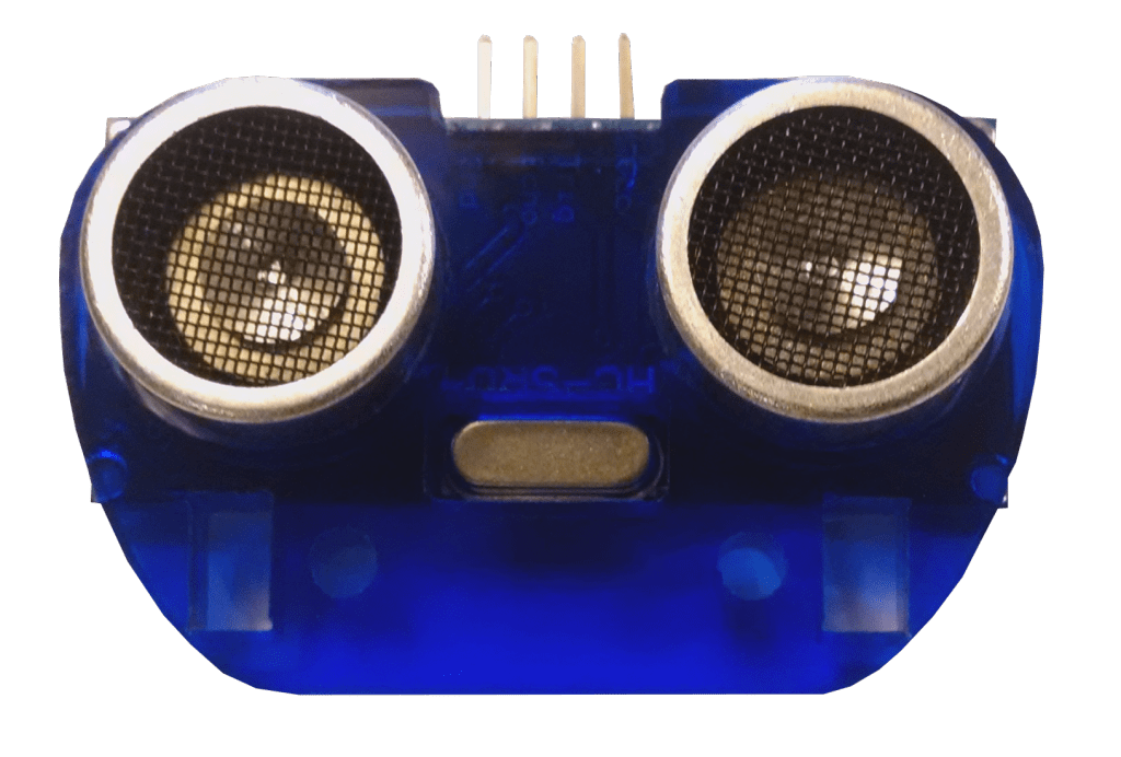
Next, take the ‘face’ piece and insert the ultrasonic distance sensor (eyes) with the pins pointing upwards.
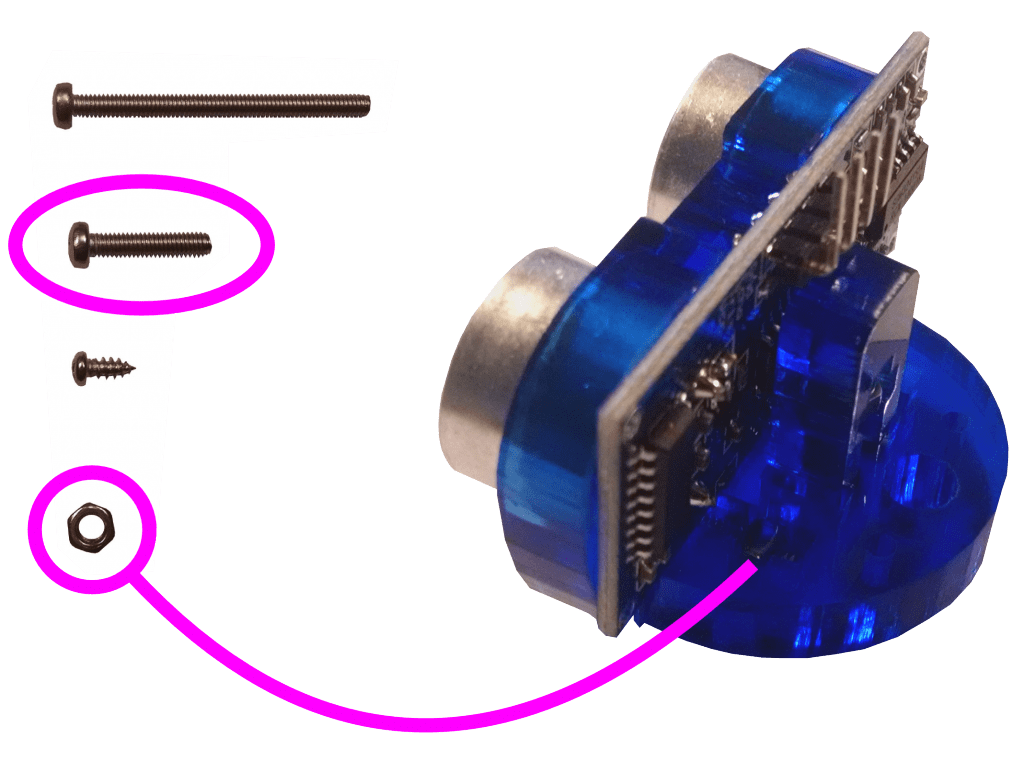
Insert the ‘head bottom’ piece into the ‘face’ piece slots, from behind, such that the smallest piece clamps the distance sensor in place. Fasten with two sets of medium bolts and nuts.
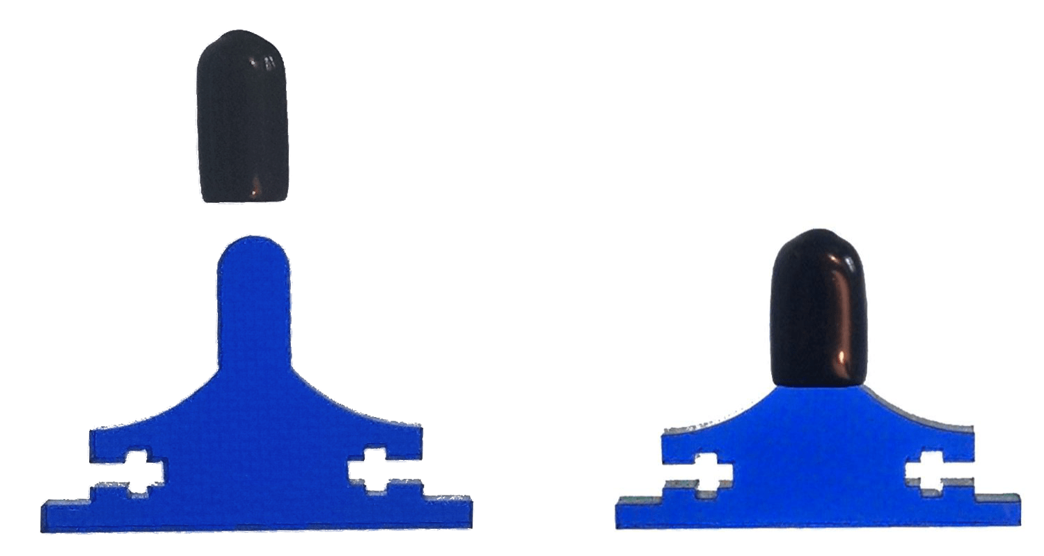
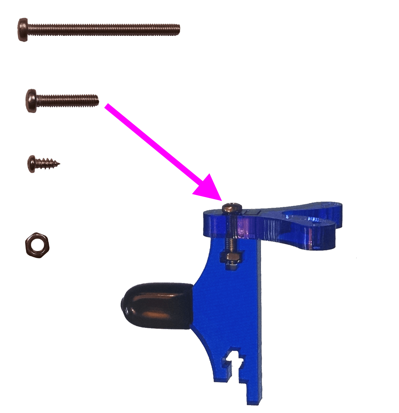
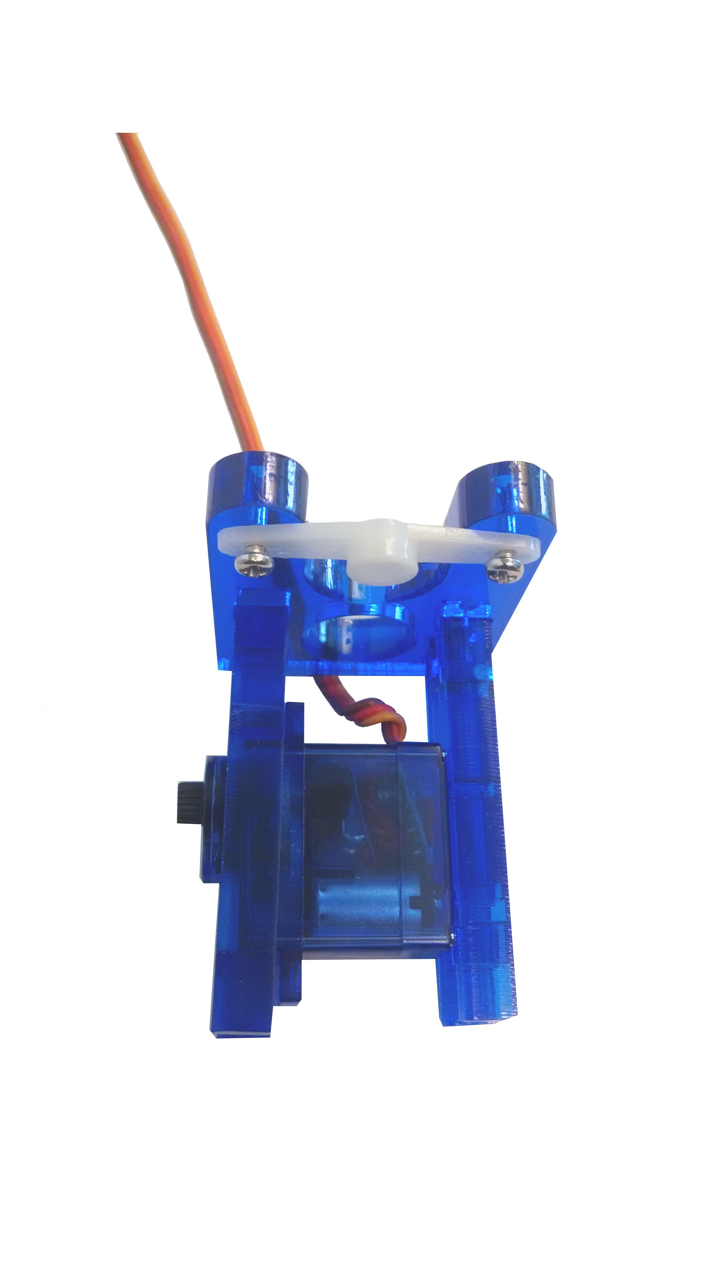
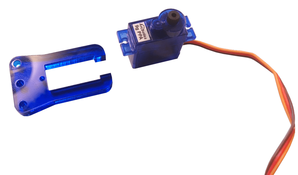
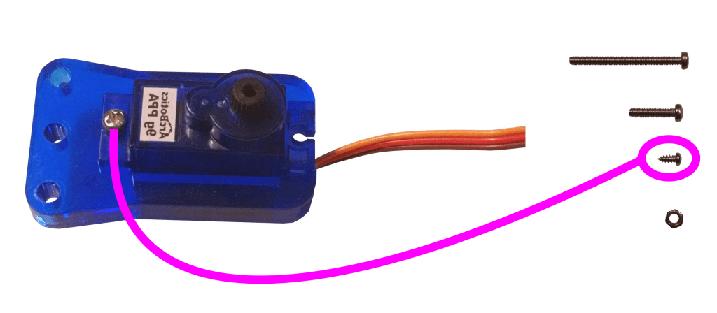
Take the servo and insert it into the C-shaped ‘neck’ piece, from above. Make sure that the cable points outwards in the direction of the ‘neck’ opening, and the servo tabs should be resting on top of the neck. Affix a small screw through the servo’s inner tab into the neck below.
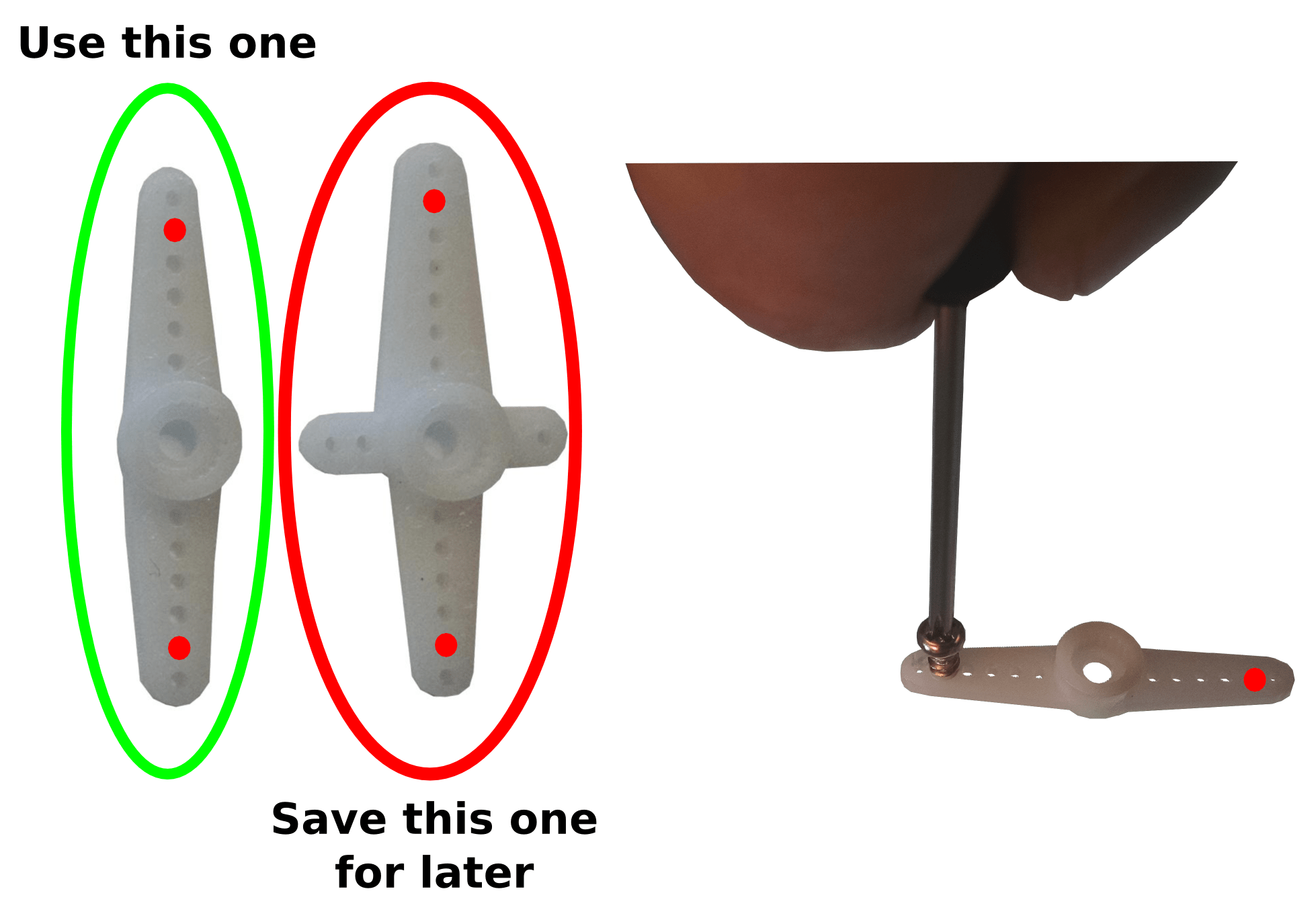
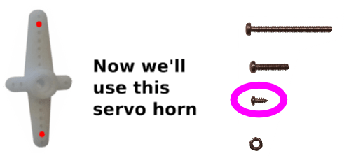
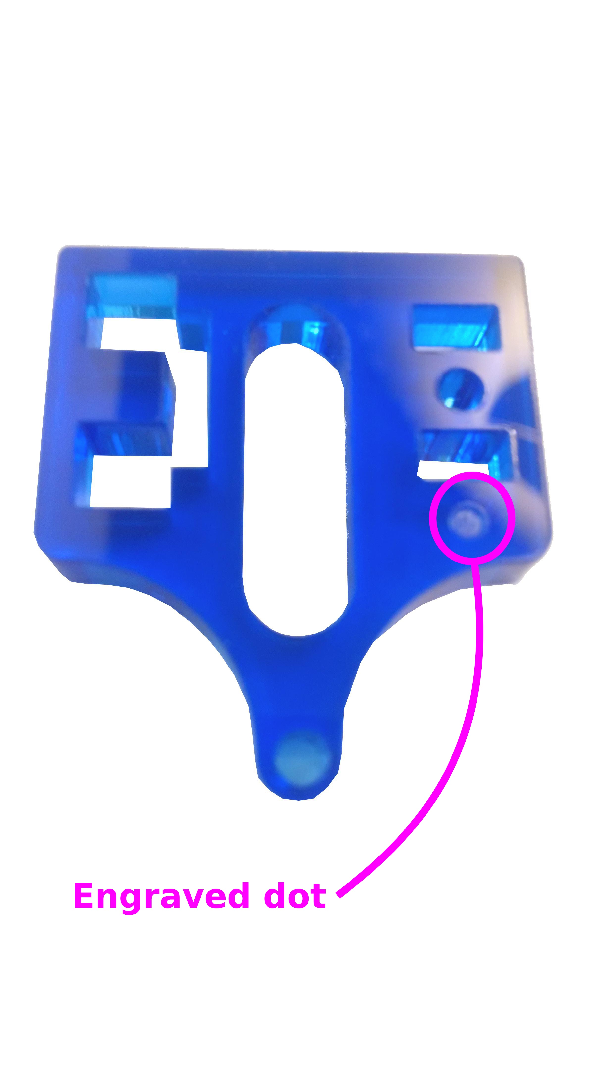
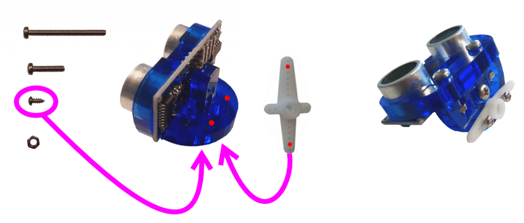
Affix a straight servo horn to the underside of the ‘head bottom’ piece through the holes indicated by the red dots in the image. The parts before attachment are shown on the left and the completed part is shown on the right.
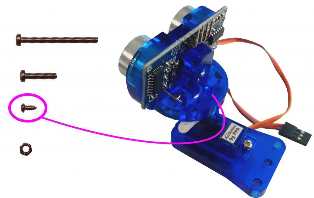
Power and center the head servo as you have been doing with the others. Then, gently push the servo’s axle into the servo horn on the bottom of the head. Insert a small screw into the hole in the head and tighten it to finish attaching the head to the servo.
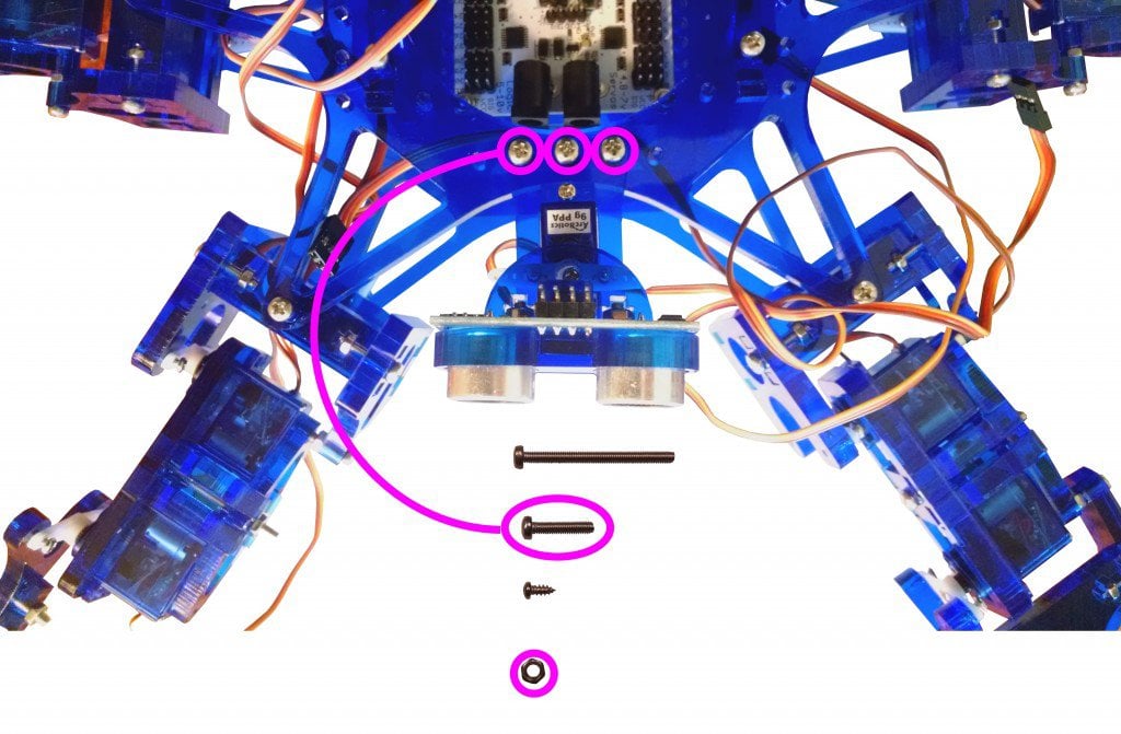
The head segment attaches to the top of the body framework, above the battery plug on the controller. Insert three medium bolts through the ‘neck’ piece and front of the body top. Secure these bolts using nuts.
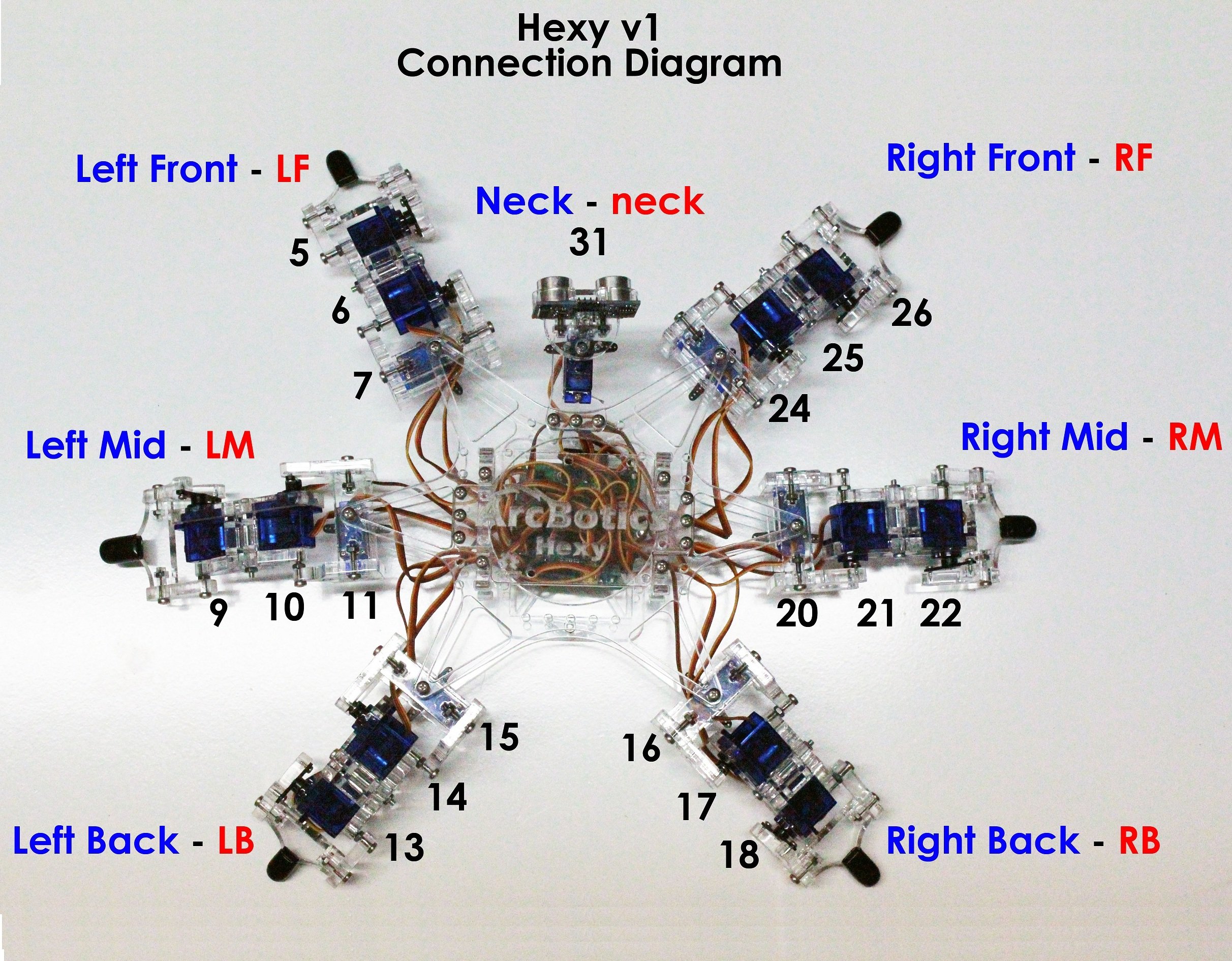
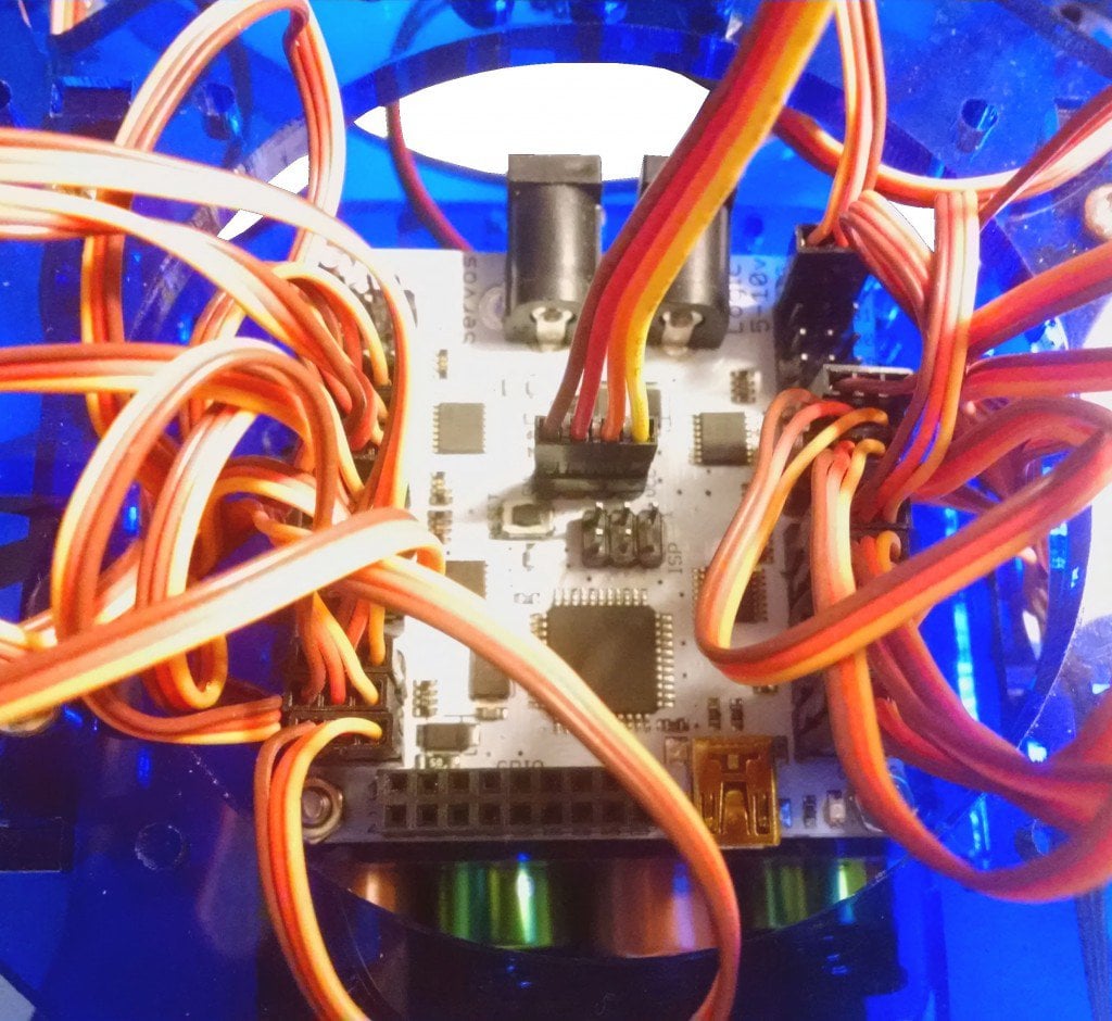
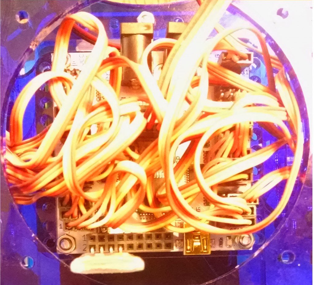
Step 3.7 – Connect the Servos
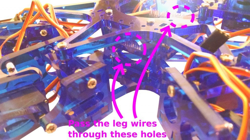
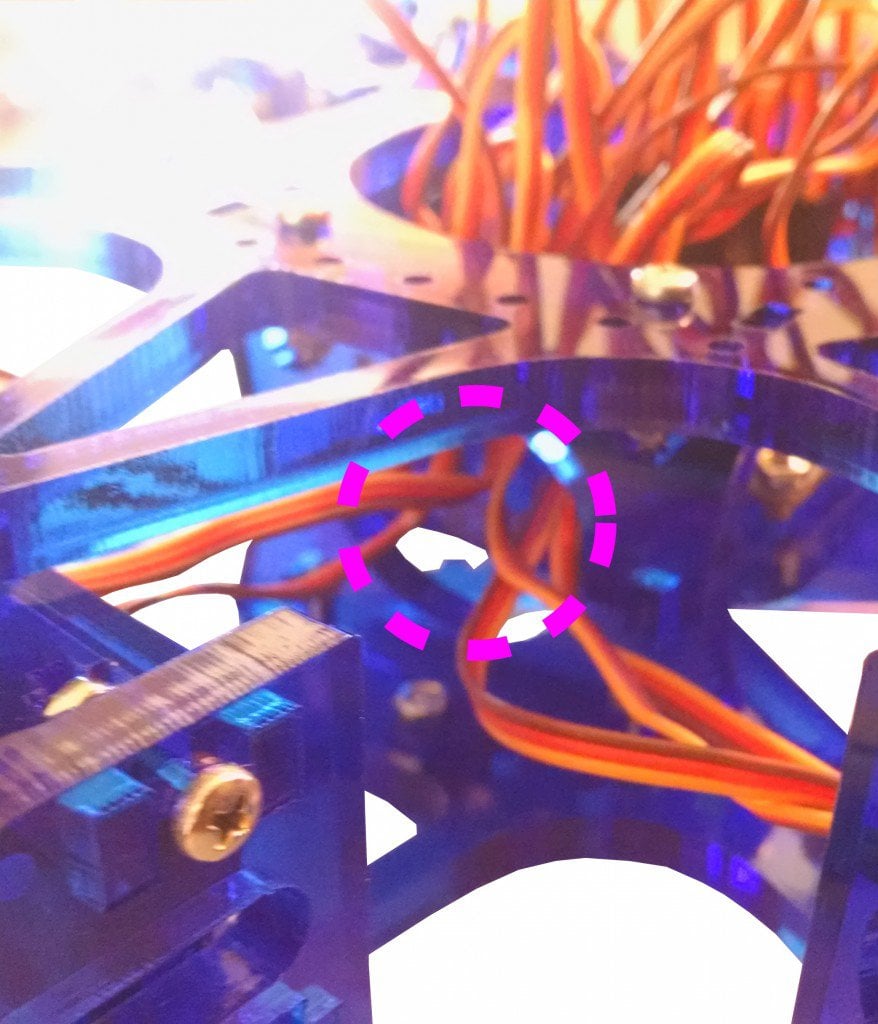
Connect the servos to the proper ports shown in the diagram below. The brown wires of the servos should be facing outwards toward the edge of the Servo Controller board. Make sure to connect the wires to the right ports. This is important so that the software will know which joint is connected to each port. If wired incorrectly, it could result in very funky movements.
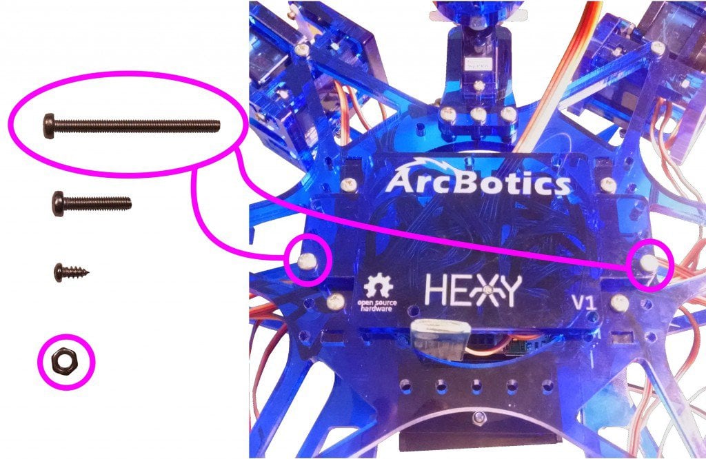
Once you have connected all the servos you can attach the Nameplate to Hexy.
But! You will probably want to attach the ultrasonic sensor and Bluetooth module to Hexy before attaching the Nameplate since you won’t be able to plug them in afterwards.
You will want to connect the ultrasonic sensor and the Bluetooth module before you do this, since it will be difficult to insert the Bluetooth module afterwards. You can attach the Nameplate using all six bolts, or you can just use two as shown. The medium sized bolts will fit (just barely), but we find that it is much easier to attach the Nameplate using the larger bolts.
Build Complete!
Step 4.0 – (optional) Attaching the Accessories
While the ultrasonics and Bluetooth are not necessary, they do give Hexy some freedom. The eyes let Hexy detect objects in front of it, and the Bluetooth lets it stay connected to the computer wirelessly.
Step 4.1 – (optional) Connect the Ultrasonic
With the Servotor32 powered, take one end of the 4-wire cable and connect connect it to ultrasonic unit, and then the other end to the board. Note the labels on the board and the ultrasonic ‘vcc’ and ‘gnd’. Make sure the wires are connecting ‘vcc’ to ‘vcc’ and ‘gnd’ to ‘gnd’. If the green light on the board starts to dim, unplug the ultrasonic immediately. This means the ultrasonic is plugged in backwards and is shorting out the board. Reverse the connection and try again.
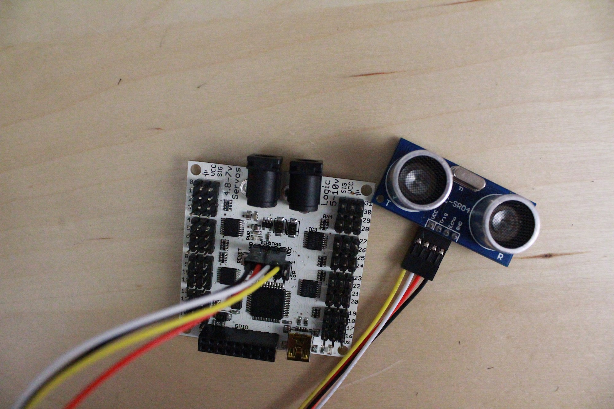
More information about working with the ultrasonic is available one the HC-SR04 Ultrasonic Distance Sensor page
First, if you’re using the module with a Servotor32, make sure you update to the latest Servotor32 firmware.
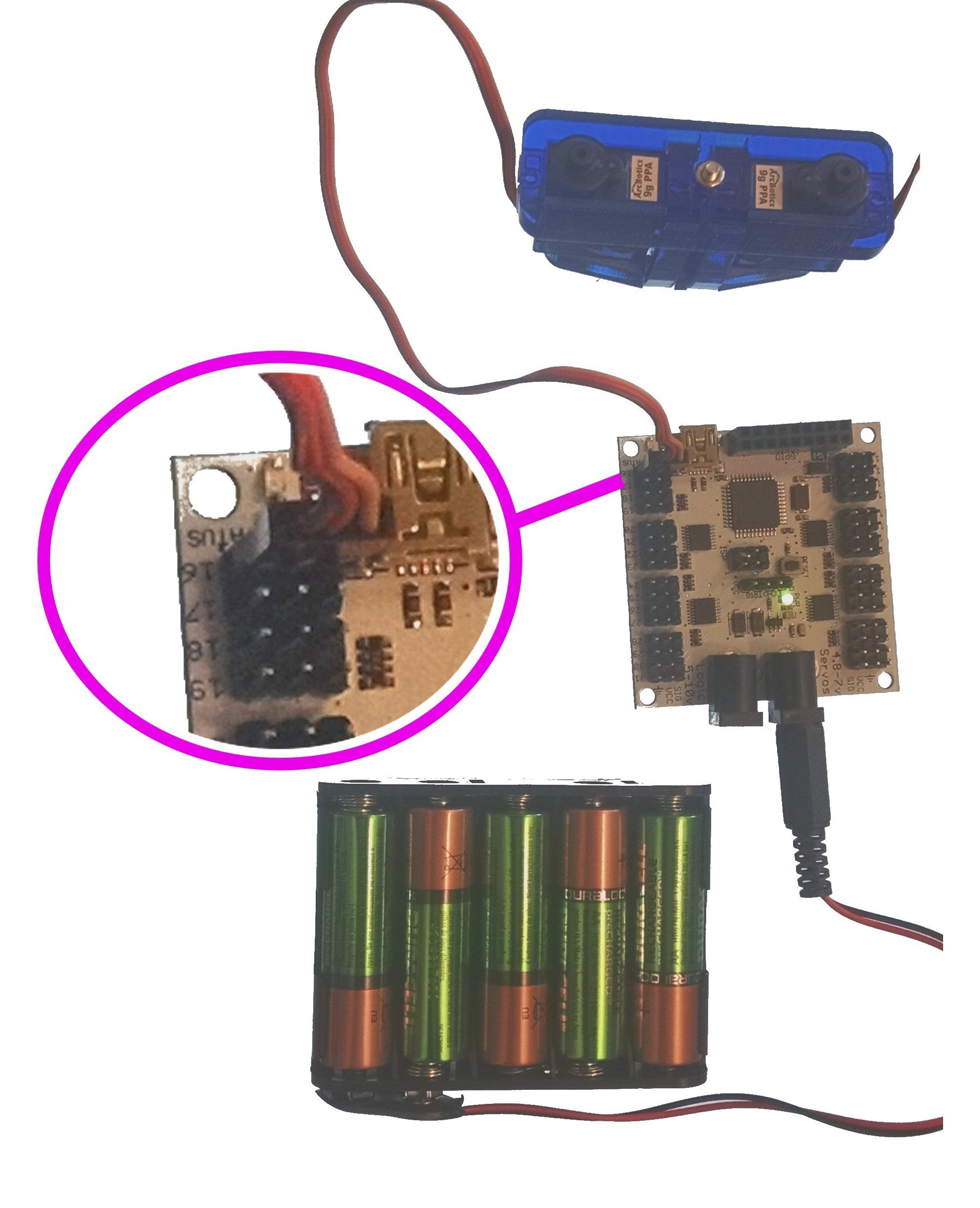
Next, turn on the Bluetooth module by providing it 3.3v or 5v of power. In this case, we’re supplying power by plugging the module into the ArcBotics Servotor32 controller board. If you have a 6-pin module, ignore all but the 4 middle pins, and plug it in as shown below:
Once you plug power into the Logic connector on the Hexy servo controller board the Bluetooth unit should be blink its red light on and off, this means it is on, but not paired with anything.
The Bluetooth is a tight fit once you attach the Nameplate. It may even bend to the side a little. That’s fine, as long as after you attach the Nameplate and power up Hexy the red LED still blinks.
You can pair by following the guide for your Operating System:
More information about the bluetooth is available on the Bluetooth 2.1 Module Page